Radio VOC sensor
This guide walks you through the Radio VOC sensor project. At the end, you'll see a dashboard in Node-RED with TVOC, temperature and humidity.
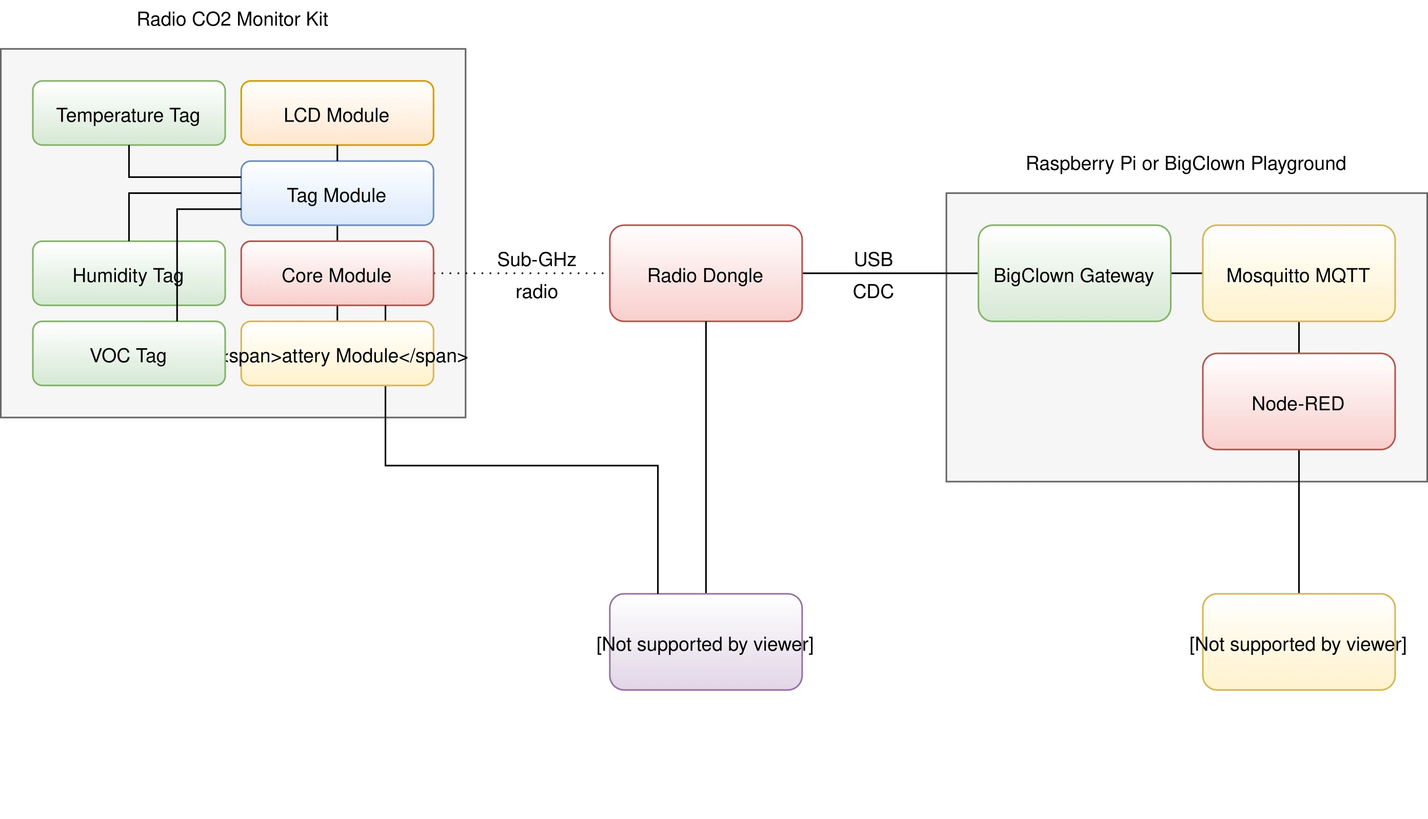
Block Diagram
Requirements
-
Required components
- 1x Core Module
- 1x VOC Tag
- 1x Battery Module
- 1x Radio Dongle
-
Optional components
- 1x LCD Module
- 1x Tag Module
- 1x Temperature Tag
- 1x Humidity Tag
-
One of the following:
- HARDWARIO Playground installed (recommended) See Playground Installation for details.
- Raspberry Pi with the HARDWARIO Raspbian distribution See Raspberry Pi Installation for details.
- HARDWARIO Toolchain installed See Command Line Tools for details.
Firmware Upload
You'll upload the firmware to the Core Module with HARDWARIO Playground.
Step 1: Connect the Core Module to your computer with a Micro USB cable
Step 2: Upload the firmware
Start HARDWARIO Playground, select the bcf-radio-voc-sensor firmware on the Firmware tab and upload it to the Core Module:
Flashing Core Module R1 and R2 The older Core Module 1 and the newer Core Module 2 are flashed differently; see Core Module R1 and R2 comparison in the Hardware section.
Step 3: Disconnect the Micro USB cable from the Core Module and the computer
Your firmware is now uploaded.
Hardware Assembly
Minimal Hardware
This is the minimal assembly for the VOC sensor.
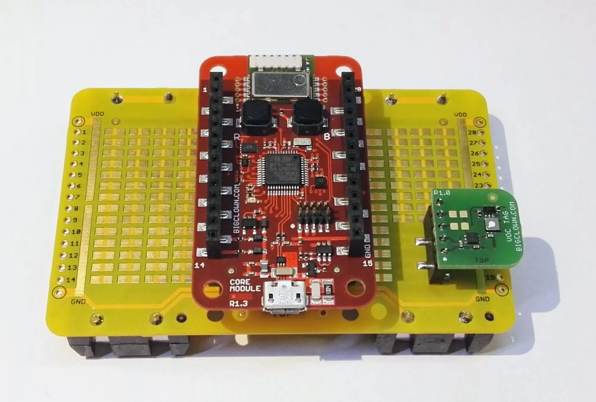
Step 1: Start with the Battery Module
Check that there are no batteries in the Battery Module yet.
Step 2: Plug the VOC Tag onto the Battery Module
Step 3: Plug the Core Module onto the Battery Module
Full Hardware
The firmware also supports LCD Module, Tag Module, Temperature Tag and Humidity Tag. All values are shown as clear graphs on the display and also sent over the HARDWARIO radio network to the Radio Dongle.
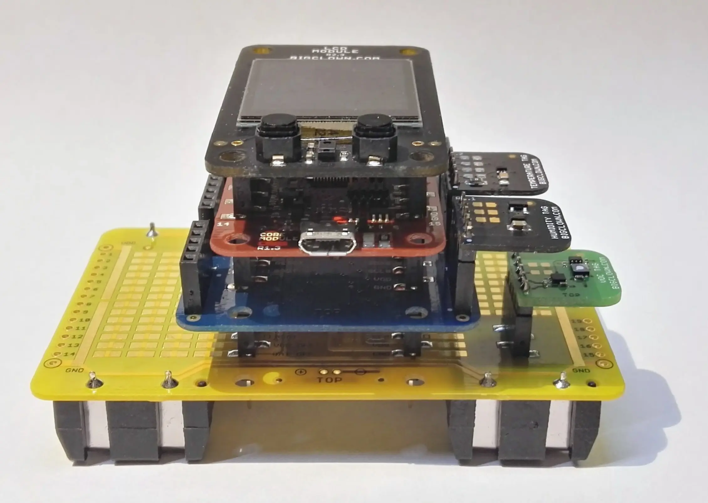
Step 1: Start with the Battery Module
Check that there are no batteries in the Battery Module yet.
Step 2: Plug the VOC Tag onto the Battery Module
Step 3: Plug the Tag Module onto the Battery Module
Step 4: Plug the Temperature Tag and Humidity Tag into the sockets on the Tag Module
Step 5: Plug the Core Module onto the Tag Module
Step 6: Plug the LCD Module onto the Core Module
Playground Setup
If you use the new HARDWARIO Playground, open the Functions tab instead of http://localhost:1880/. Pairing now happens on the Devices tab, and you test communication on the Messages tab.
Step 1: Open Node-RED in your web browser
Step 2: You should see an empty workspace with Flow 1
Step 3: Import the following snippet into the flow (Menu >> Import) and click the Flow 1 tab
[{"id":"2fc604fc.3b6abc","type":"inject","z":"dfc861b.b2a02a","name":"List all gateways","topic":"gateway/all/info/get","payload":"","payloadType":"str","repeat":"","crontab":"","once":false,"x":560,"y":460,"wires":[["a2c10833.24d5d8"]]},{"id":"1e4502b8.2f63fd","type":"inject","z":"dfc861b.b2a02a","name":"Start node pairing","topic":"gateway/usb-dongle/pairing-mode/start","payload":"","payloadType":"str","repeat":"","crontab":"","once":false,"x":570,"y":580,"wires":[["795ff5a7.8e266c"]]},{"id":"3d844ce2.932864","type":"inject","z":"dfc861b.b2a02a","name":"Stop node pairing","topic":"gateway/usb-dongle/pairing-mode/stop","payload":"","payloadType":"str","repeat":"","crontab":"","once":false,"x":560,"y":640,"wires":[["5967c452.c838bc"]]},{"id":"f202b253.2705b","type":"inject","z":"dfc861b.b2a02a","name":"List paired nodes","topic":"gateway/usb-dongle/nodes/get","payload":"","payloadType":"str","repeat":"","crontab":"","once":false,"x":560,"y":520,"wires":[["f0aca138.0b2c3"]]},{"id":"349f02fd.890f6e","type":"inject","z":"dfc861b.b2a02a","name":"Unpair all nodes","topic":"gateway/usb-dongle/nodes/purge","payload":"","payloadType":"str","repeat":"","crontab":"","once":false,"x":560,"y":700,"wires":[["2f1c5bb6.53d6f4"]]},{"id":"cf61d75d.4ad8f8","type":"mqtt in","z":"dfc861b.b2a02a","name":"","topic":"#","qos":"2","broker":"67b8de4a.029d3","x":530,"y":400,"wires":[["a5cb0658.f5d658"]]},{"id":"a5cb0658.f5d658","type":"debug","z":"dfc861b.b2a02a","name":"","active":true,"console":"false","complete":"false","x":790,"y":400,"wires":[]},{"id":"a2c10833.24d5d8","type":"mqtt out","z":"dfc861b.b2a02a","name":"","topic":"","qos":"","retain":"","broker":"717f7c18.ba0a24","x":770,"y":460,"wires":[]},{"id":"f0aca138.0b2c3","type":"mqtt out","z":"dfc861b.b2a02a","name":"","topic":"","qos":"","retain":"","broker":"717f7c18.ba0a24","x":770,"y":520,"wires":[]},{"id":"795ff5a7.8e266c","type":"mqtt out","z":"dfc861b.b2a02a","name":"","topic":"","qos":"","retain":"","broker":"717f7c18.ba0a24","x":770,"y":580,"wires":[]},{"id":"5967c452.c838bc","type":"mqtt out","z":"dfc861b.b2a02a","name":"","topic":"","qos":"","retain":"","broker":"717f7c18.ba0a24","x":770,"y":640,"wires":[]},{"id":"2f1c5bb6.53d6f4","type":"mqtt out","z":"dfc861b.b2a02a","name":"","topic":"","qos":"","retain":"","broker":"717f7c18.ba0a24","x":770,"y":700,"wires":[]},{"id":"67b8de4a.029d3","type":"mqtt-broker","z":"","broker":"127.0.0.1","port":"1883","clientid":"","usetls":false,"compatmode":true,"keepalive":"60","cleansession":true,"willTopic":"","willQos":"0","willPayload":"","birthTopic":"","birthQos":"0","birthPayload":""},{"id":"717f7c18.ba0a24","type":"mqtt-broker","z":"","broker":"127.0.0.1","port":"1883","clientid":"","usetls":false,"compatmode":true,"keepalive":"60","cleansession":true,"willTopic":"","willQos":"0","willPayload":"","birthTopic":"","birthQos":"0","birthPayload":""}]
It looks like this:
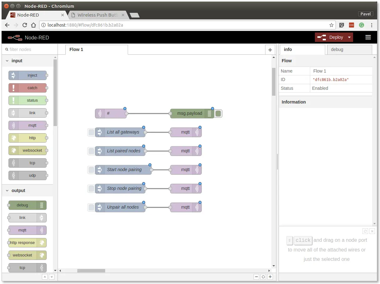
The snippet adds buttons for the gateway and radio commands, which are sent over MQTT.
Step 4: Deploy the flow with the Deploy button in the top-right corner
Step 5: Open the debug tab
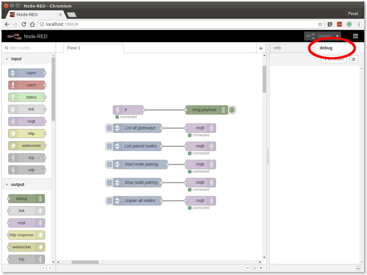
The debug tab shows all MQTT messages.
Step 6: Click the List all gateways button. The debug tab should show a response like this
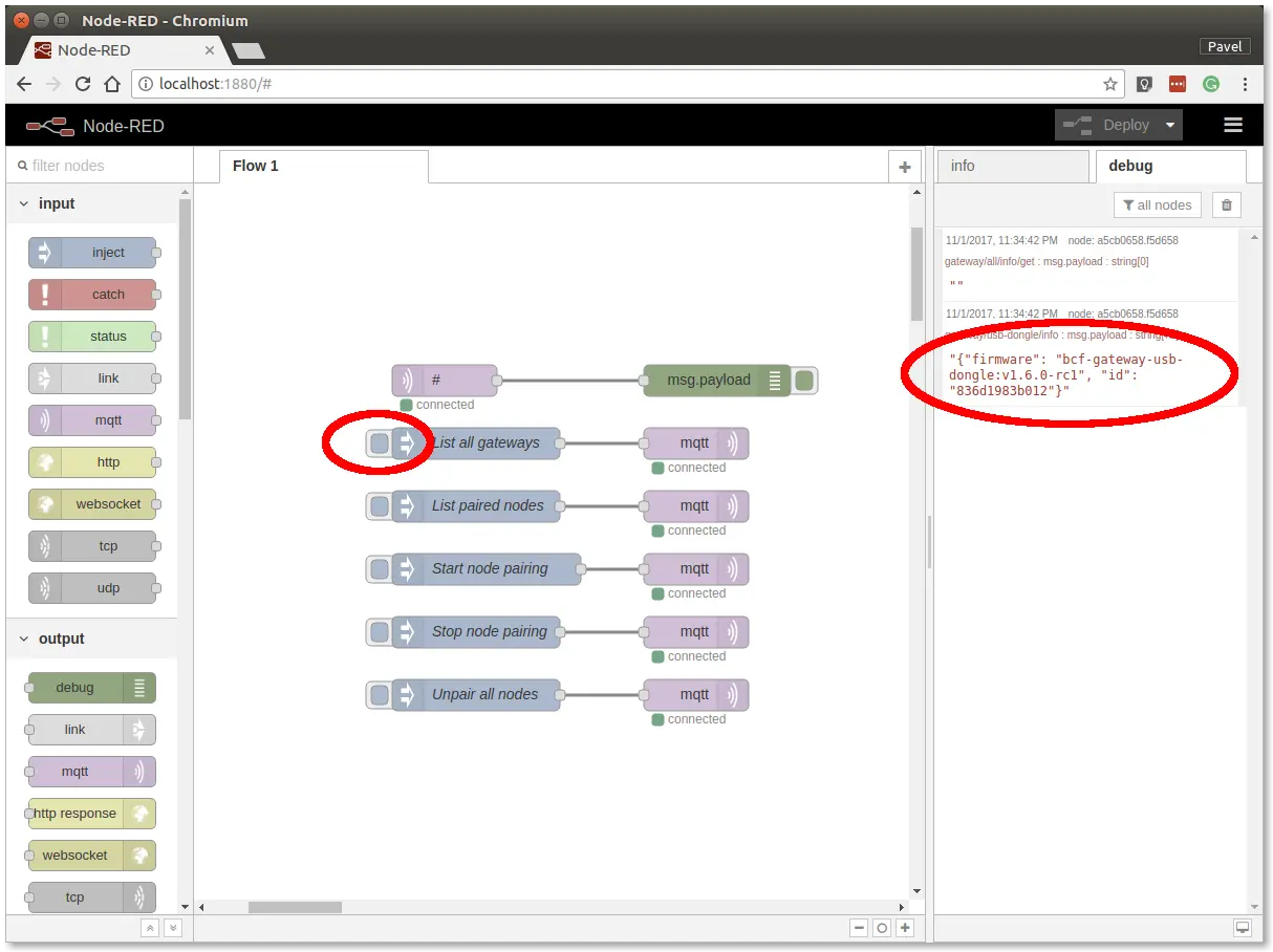
You now have working Node-RED, MQTT, HARDWARIO Radio Dongle and HARDWARIO Gateway.
Radio Pairing
In this section, we'll establish a radio link between the Radio Dongle and the Radio VOC sensor.
In Node-RED, follow these steps:
Step 1: Click the Start node pairing button
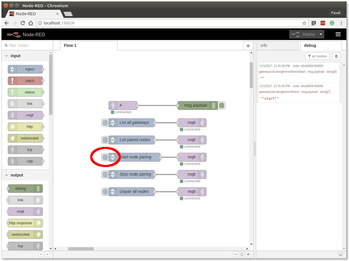
Step 2: Insert the batteries
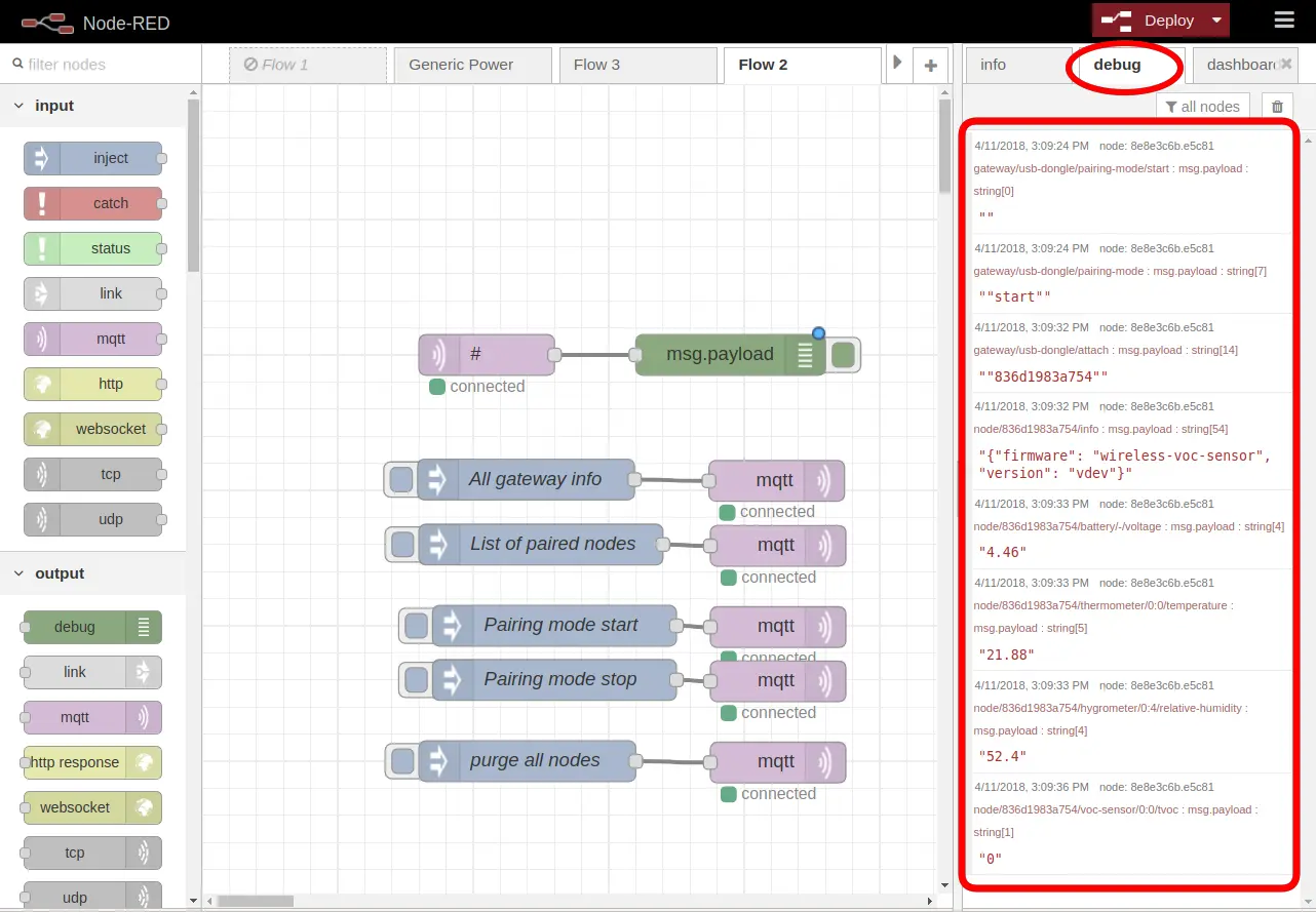
Insert the batteries into the Radio VOC sensor to send the pairing request (the red LED on the Core Module should also light up for about 2 seconds). If you switch Node-RED to the debug tab on the right, you'll see a pairing response like this:
Step 3: Click the Stop node pairing button
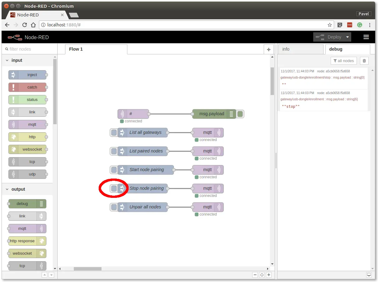
You now have a radio link between the node (Radio VOC sensor) and the gateway (Radio Dongle).
Communication Test
In Node-RED, follow these steps:
Step 1: Switch to the debug tab on the right
Step 2: Watch the incoming data
It can take up to a minute before the VOC Tag starts sending correct values. Once the debug tab in Node-RED shows values other than zero (0), try breathing on the VOC sensor and you'll see much higher values.
You should then see messages like these:

Radio communication is now verified.
Dashboard Setup
Now let's create a dashboard in Node-RED with three gauges that show the sensor values.
Instead of following the steps below, you can import this snippet into the flow (Menu >> Import). You still have to change the MQTT topics to match the address of your radio node.
[{"id":"7018e288.6b887c","type":"ui_gauge","z":"ddfb24d2.43ab28","name":"","group":"d493d306.06098","order":0,"width":0,"height":0,"gtype":"gage","title":"Gauge","label":"units","format":"{{value}}","min":0,"max":"200","colors":["#00b500","#e6e600","#ca3838"],"seg1":"","seg2":"","x":610,"y":300,"wires":[]},{"id":"c6695f10.80722","type":"ui_gauge","z":"ddfb24d2.43ab28","name":"","group":"d493d306.06098","order":0,"width":0,"height":0,"gtype":"gage","title":"Gauge","label":"units","format":"{{value}}","min":"10","max":"30","colors":["#00b500","#e6e600","#ca3838"],"seg1":"","seg2":"","x":610,"y":360,"wires":[]},{"id":"70a87b55.8df274","type":"ui_gauge","z":"ddfb24d2.43ab28","name":"","group":"d493d306.06098","order":0,"width":0,"height":0,"gtype":"gage","title":"Gauge","label":"units","format":"{{value}}","min":0,"max":"100","colors":["#00b500","#e6e600","#ca3838"],"seg1":"","seg2":"","x":610,"y":420,"wires":[]},{"id":"fbc3fd9a.b2e59","type":"mqtt in","z":"ddfb24d2.43ab28","name":"","topic":"node/836d1983a754/voc-sensor/0:0/tvoc","qos":"2","broker":"83f37d33.4979e","x":220,"y":300,"wires":[["7018e288.6b887c"]]},{"id":"4745398e.bacaf8","type":"mqtt in","z":"ddfb24d2.43ab28","name":"","topic":"node/836d1983a754/hygrometer/0:4/relative-humidity","qos":"2","broker":"83f37d33.4979e","x":260,"y":420,"wires":[["70a87b55.8df274"]]},{"id":"92e3a555.616f58","type":"mqtt in","z":"ddfb24d2.43ab28","name":"","topic":"node/836d1983a754/thermometer/0:0/temperature","qos":"2","broker":"83f37d33.4979e","x":250,"y":360,"wires":[["c6695f10.80722"]]},{"id":"d493d306.06098","type":"ui_group","z":"","name":"Default","tab":"afe7e4c8.941208","disp":true,"width":"6","collapse":false},{"id":"83f37d33.4979e","type":"mqtt-broker","z":"","broker":"127.0.0.1","port":"1883","clientid":"","usetls":false,"compatmode":true,"keepalive":"60","cleansession":true,"willTopic":"","willQos":"0","willPayload":"","birthTopic":"","birthQos":"0","birthPayload":""},{"id":"afe7e4c8.941208","type":"ui_tab","z":"","name":"Home","icon":"dashboard"}]
Step 1: Add three mqtt in nodes from the network section
Step 2: Add three Gauge nodes from the dashboard section. Open each one and set the correct Group and Range values
Step 3: Wire each mqtt in node to one Gauge node
Step 4: Set the correct MQTT topics in all three mqtt in nodes
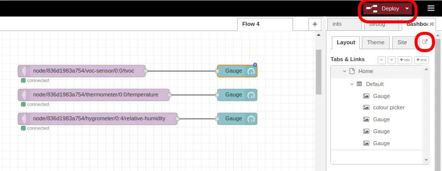
Step 5: The nodes should look like the image below
Step 6: Click Deploy, then on the dashboard tab click the small square with an arrow to open the dashboard
Dashboard
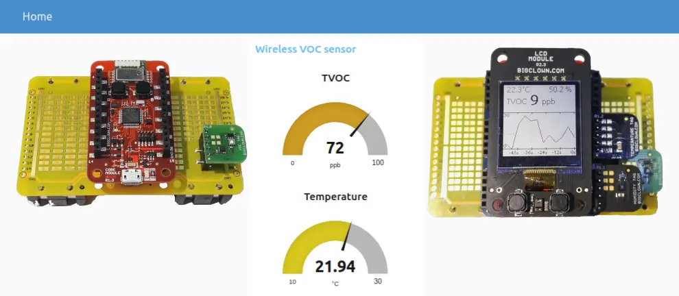
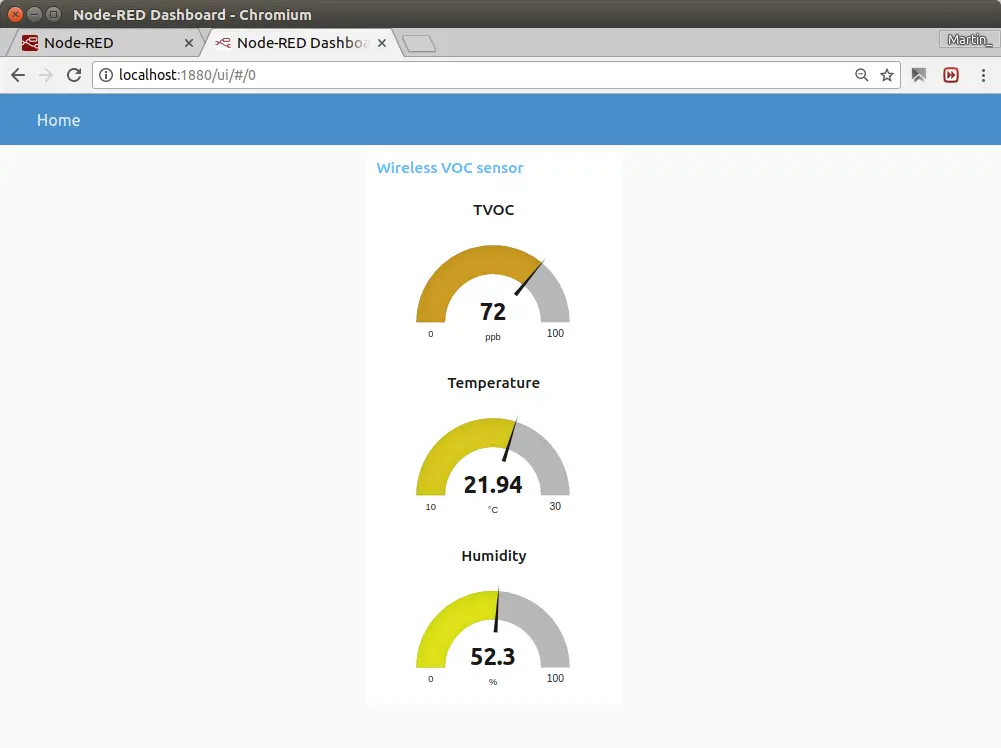
You'll see this dashboard with values from the Radio VOC sensor.
Your project is finished, congratulations!