Radio Climate Monitor
This document will guide you through the Radio Climate Monitor project. You will be able to see dashboard with temperature, humidity, ambient light and atmospheric pressure in Node-RED and view the data on your smart phone using the Blynk cloud and mobile app.
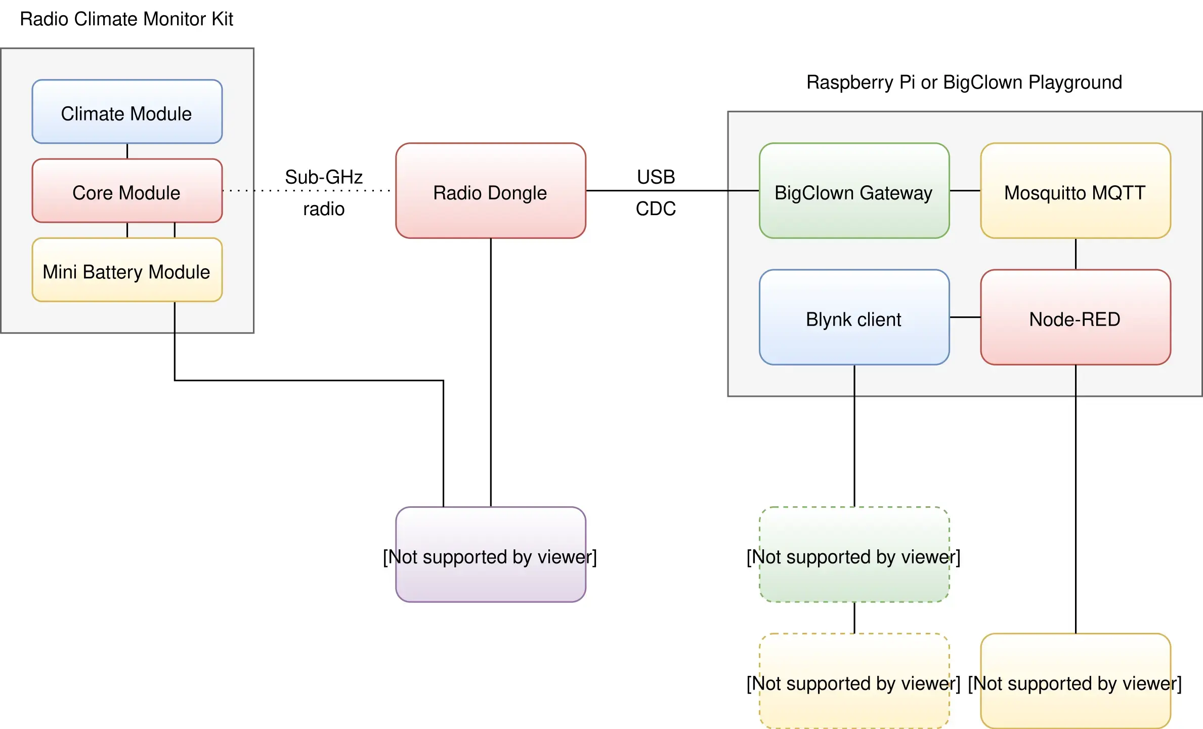
Block Concept
Requirements
-
Either Clime Set, or individual components:
- 1x Climate Module
- 1x Core Module
- 1x Mini Battery Module
- 1x Radio Dongle
-
One of these options:
- HARDWARIO Playground installed (recommended) You can find more information in the Quick Start Guide document.
- Raspberry Pi with the HARDWARIO Raspbian distribution You can find more information in the document Raspberry Pi Installation.
- HARDWARIO Toolchain installed You can find more information in the document Toolchain Setup.
Firmware Upload
In this procedure we will use the HARDWARIO Playground to upload firmware to the Core Module.
Step 1: Connect the Micro USB cable to the Core Module and your computer
Step ****2: Run the HARDWARIO Playground. In the Firmware tab choose and upload the bcf-radio-climate-monitor firmware to the Core Module
Flashing Core Module R1 & R2 For differences of flashing older Core Module 1 and newer Core Module 2 please read Core Module R1 and R2 comparison in the Hardware section
Step 3: Remove the Micro USB cable from the Core Module and your computer
At this point your firmware is successfully uploaded.
Hardware Assembling
See short video with easy step by step demonstration:
Step 1: Start with the Mini Battery Module
Make sure the Mini Battery Module does not have batteries inserted.
Step 2: Plug the Core Module on top of the Mini Battery Module
Step 3: Plug the Climate Module on top of the Core Module
Playground Bootstrap
If you are using the new HARDWARIO Playground, then use the Functions tab instead of using http://localhost:1880/. Also the pairing process is now done in Devices tab. For communication test use the Messages tab.
Step 1: Open Node-RED in your web browser
Step 2: You should see the empty workspace with Flow 1
Step 3: Insert the following snippet in the flow (using Menu >> Import) and click in Flow 1 tab
[{"id":"2fc604fc.3b6abc","type":"inject","z":"dfc861b.b2a02a","name":"List all gateways","topic":"gateway/all/info/get","payload":"","payloadType":"str","repeat":"","crontab":"","once":false,"x":560,"y":460,"wires":[["a2c10833.24d5d8"]]},{"id":"1e4502b8.2f63fd","type":"inject","z":"dfc861b.b2a02a","name":"Start node pairing","topic":"gateway/usb-dongle/pairing-mode/start","payload":"","payloadType":"str","repeat":"","crontab":"","once":false,"x":570,"y":580,"wires":[["795ff5a7.8e266c"]]},{"id":"3d844ce2.932864","type":"inject","z":"dfc861b.b2a02a","name":"Stop node pairing","topic":"gateway/usb-dongle/pairing-mode/stop","payload":"","payloadType":"str","repeat":"","crontab":"","once":false,"x":560,"y":640,"wires":[["5967c452.c838bc"]]},{"id":"f202b253.2705b","type":"inject","z":"dfc861b.b2a02a","name":"List paired nodes","topic":"gateway/usb-dongle/nodes/get","payload":"","payloadType":"str","repeat":"","crontab":"","once":false,"x":560,"y":520,"wires":[["f0aca138.0b2c3"]]},{"id":"349f02fd.890f6e","type":"inject","z":"dfc861b.b2a02a","name":"Unpair all nodes","topic":"gateway/usb-dongle/nodes/purge","payload":"","payloadType":"str","repeat":"","crontab":"","once":false,"x":560,"y":700,"wires":[["2f1c5bb6.53d6f4"]]},{"id":"cf61d75d.4ad8f8","type":"mqtt in","z":"dfc861b.b2a02a","name":"","topic":"#","qos":"2","broker":"67b8de4a.029d3","x":530,"y":400,"wires":[["a5cb0658.f5d658"]]},{"id":"a5cb0658.f5d658","type":"debug","z":"dfc861b.b2a02a","name":"","active":true,"console":"false","complete":"false","x":790,"y":400,"wires":[]},{"id":"a2c10833.24d5d8","type":"mqtt out","z":"dfc861b.b2a02a","name":"","topic":"","qos":"","retain":"","broker":"717f7c18.ba0a24","x":770,"y":460,"wires":[]},{"id":"f0aca138.0b2c3","type":"mqtt out","z":"dfc861b.b2a02a","name":"","topic":"","qos":"","retain":"","broker":"717f7c18.ba0a24","x":770,"y":520,"wires":[]},{"id":"795ff5a7.8e266c","type":"mqtt out","z":"dfc861b.b2a02a","name":"","topic":"","qos":"","retain":"","broker":"717f7c18.ba0a24","x":770,"y":580,"wires":[]},{"id":"5967c452.c838bc","type":"mqtt out","z":"dfc861b.b2a02a","name":"","topic":"","qos":"","retain":"","broker":"717f7c18.ba0a24","x":770,"y":640,"wires":[]},{"id":"2f1c5bb6.53d6f4","type":"mqtt out","z":"dfc861b.b2a02a","name":"","topic":"","qos":"","retain":"","broker":"717f7c18.ba0a24","x":770,"y":700,"wires":[]},{"id":"67b8de4a.029d3","type":"mqtt-broker","z":"","broker":"127.0.0.1","port":"1883","clientid":"","usetls":false,"compatmode":true,"keepalive":"60","cleansession":true,"willTopic":"","willQos":"0","willPayload":"","birthTopic":"","birthQos":"0","birthPayload":""},{"id":"717f7c18.ba0a24","type":"mqtt-broker","z":"","broker":"127.0.0.1","port":"1883","clientid":"","usetls":false,"compatmode":true,"keepalive":"60","cleansession":true,"willTopic":"","willQos":"0","willPayload":"","birthTopic":"","birthQos":"0","birthPayload":""}]
It will look like this:
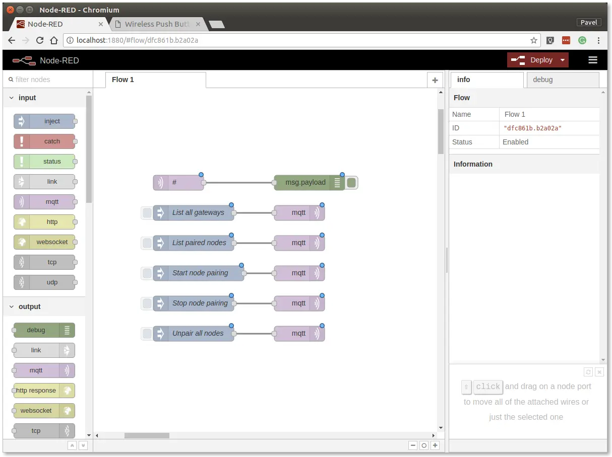
This snippet provides control buttons for gateway/radio commands. These commands are sent over the MQTT protocol.
Step 4: Deploy the flow using the Deploy button in the top-right corner
Step 5: Open the debug tab
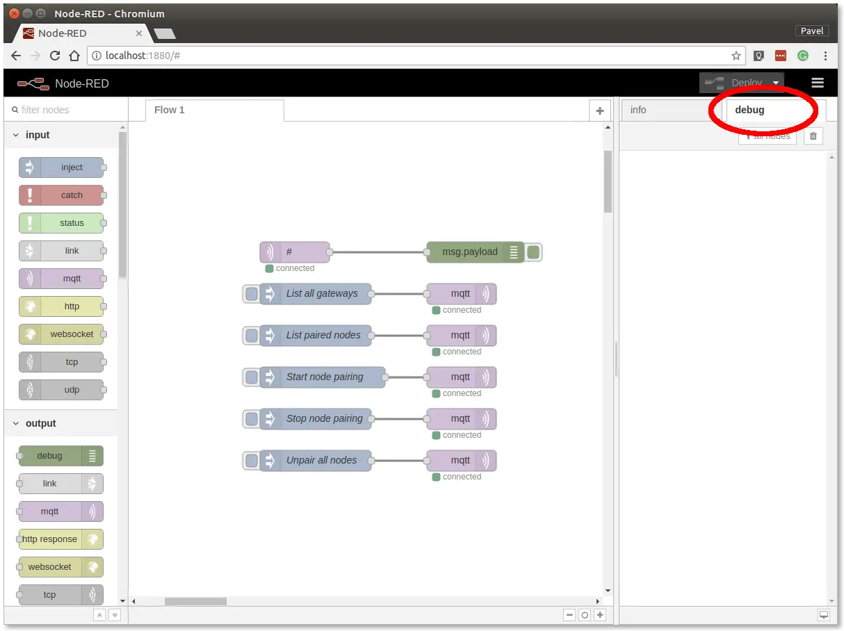
In the debug tab, you will be able to see all the MQTT messages.
Step 6: Click on the List all gateways button. You should see a response like this in the debug tab
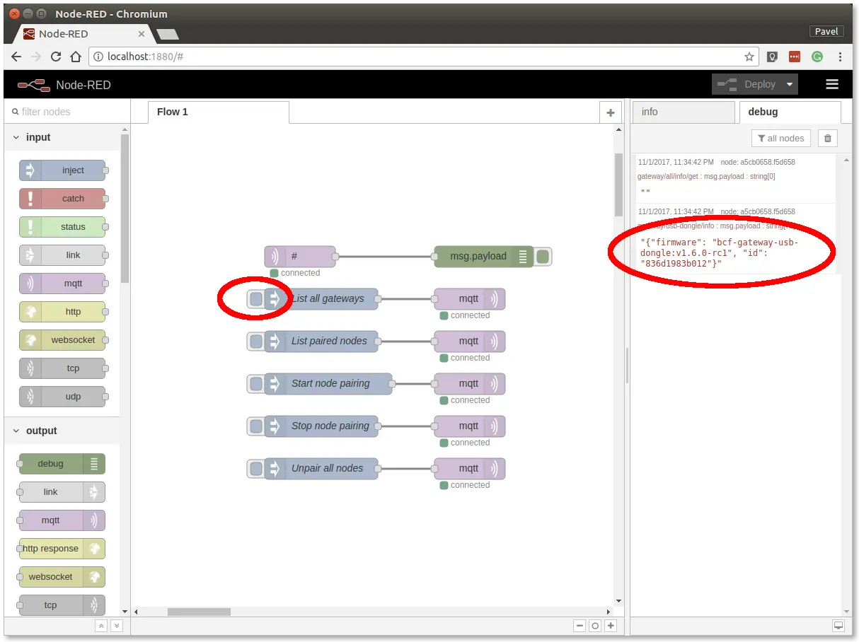
At this point, you've got working Node-RED, MQTT, HARDWARIO Radio Dongleand HARDWARIO Gateway.
Radio Pairing
In this section, we will create a radio link between the Radio Dongle and the Radio Climate Monitor.
Follow these steps in Node-RED:
Step 1: Click on the Start node pairing button
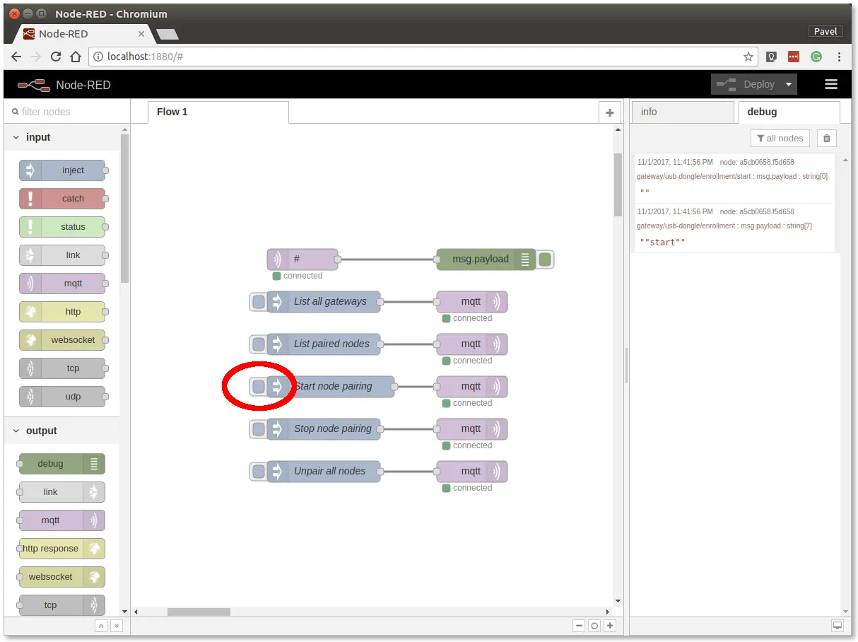
Step 2: Pair Climate Monitor
Insert the batteries into the Radio Climate Monitor to send the pairing request (you should also see the red LED on the Core Module to be on for about 2 seconds).
Step 3: Click on the Stop node pairing button
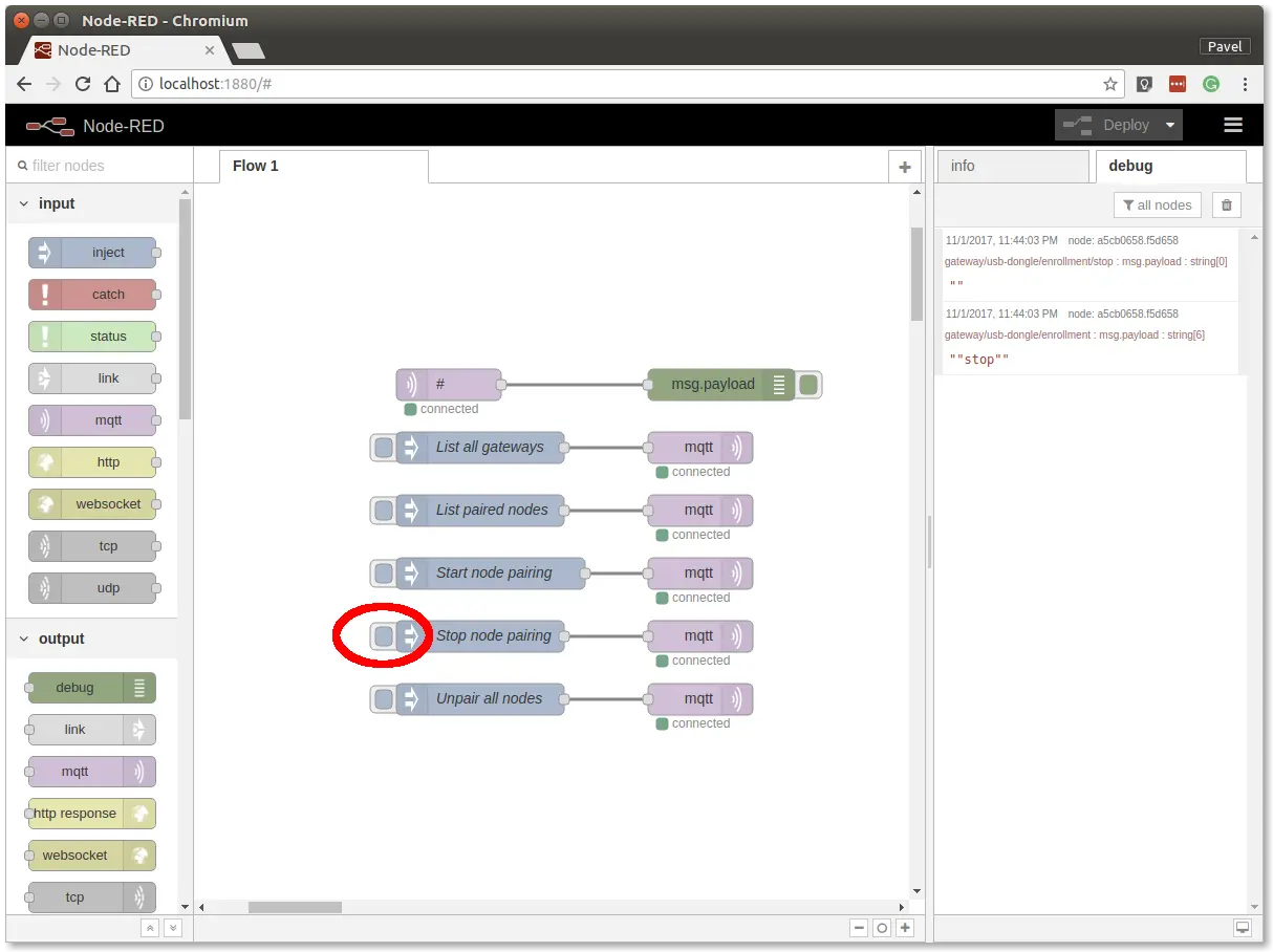
At this point, you've got established a radio link between the node (Radio Climate Monitor) and the gateway (Radio Dongle).
Communication Test
Follow these steps in Node-RED:
Step 1: Switch to debug tab on the right
Step 2: Test connection
Start breathing on the temperature sensor on the Climate Module to invoke a change of temperature and hence trigger a radio transmission.
You should then see similar messages:
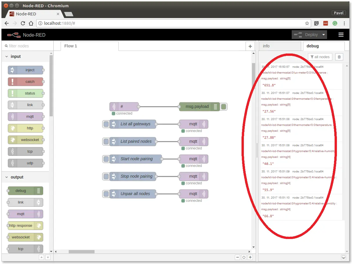
At this point, you've got verified radio communication.
Enclosure
Optionally put the assembly into the appropriate enclosure, if you have one.
You can find more information about the enclosures in the document Enclosures.
Integration with Blynk IoT
Now that the kit is assembled and sending data over MQTT, let's push the sensor values to your phone with Blynk IoT (the current Blynk platform — the old Blynk Legacy app and its blynk-cloud.com cloud have been shut down). You'll create an account, a device template, and one Datastream per measured value, then wire those datastreams in Node-RED with the Blynk IoT Write node.
For the click-by-click account, template, and device setup, follow the canonical guide:
Blynk app integration — HARDWARIO docs
Step 1: Create the Blynk IoT account, template, and device
If you don't have one yet, create a Blynk IoT account, then create a device template and a device from it. The guide above walks through each of these. From the device detail you'll need its Auth Token and Template ID in a later step.
Step 2: Create one Datastream (Virtual Pin) per value
On the template, open the Datastreams tab and add one Virtual Pin datastream for each value. Use the Double data type for all of them and set sensible units and ranges:
| Datastream | Virtual Pin | Type | Unit | Suggested range |
|---|---|---|---|---|
| Illuminance | V0 | Double | lux | 0 – 1000 |
| Temperature | V1 | Double | °C | 0 – 50 |
| Relative humidity | V2 | Double | % | 0 – 100 |
| Atmospheric pressure | V3 | Double | Pa | 80000 – 110000 |
The Virtual Pin numbers above must match the Virtual Pin you set on each Node-RED Write node in the next step.
Step 3: Wire the values in Node-RED with the Blynk IoT Write node
Add a new Flow (the big plus button next to the flow name), then for each value place an mqtt in node subscribed to the sensor topic followed by a green Blynk IoT → write node. Connect each mqtt in node to its write node:
node/climate-monitor:0/lux-meter/0:0/illuminance        →  Write V0
node/climate-monitor:0/thermometer/0:0/temperature      →  Write V1
node/climate-monitor:0/hygrometer/0:4/relative-humidity →  Write V2
node/climate-monitor:0/barometer/0:0/pressure           →  Write V3
If you want to use this for other sensors, just change the MQTT topics.
Step 4: Configure the Blynk IoT connection
Double-click a Write node to open it. On the right, click the pencil to edit the Blynk IoT connection. In the Url field enter blynk.cloud, and copy the Auth Token and Template ID from your device detail in the Blynk IoT web console. Confirm with Add.
Back in the node, set the Virtual Pin to the number from the table above (just the number, without the letter "V"). Repeat for each Write node so its Virtual Pin matches its value, then click Deploy in the top-right corner.
Step 5: Add widgets in the Blynk IoT app
Download the Blynk IoT app from the App Store or Google Play, sign in, and open your device. Add a Gauge or Chart widget for each value and, in the widget settings, point its Datastream at the matching Virtual Pin (V0–V3). Once Node-RED is deployed, the live readings appear on your phone.