Radio Smart LED Strip
This document will guide you through the Radio Smart LED Strip project. You will be able to interact with your LED strip in Node-RED and Blynk and control Power appliance using 16A Relay.
Block Concept

Requirements
-
Either Control Set, or individual components:
- 1x Cover Module
- 1x Core Module
- 1x Power Module
- 1x AC/DC ADAPTER 5V/4A (or higher current rating)
- 1x 3D printed enclosure BCE301
-
Other components:
- 1x Radio Dongle (not included in the kit)
- 1x RGB or RGBW Digital LED strip (not included in the kit)
- Micro USB cable (not included in the kit)
-
One of these options:
- HARDWARIO Playground installed (recommended) You can find more information in the Quick Start Guide document.
- Raspberry Pi with the HARDWARIO Raspbian distribution You can find more information in the document Raspberry Pi Installation.
- HARDWARIO Firmware Tool installed You can find more information in the document Toolchain Setup.
Firmware Upload
In this procedure we will use the HARDWARIO Playground to upload firmware to the Core Module.
Step 1: Connect the Micro USB cable to the Core Module and your computer
Step 2: Flash firmware
Run the HARDWARIO Playground. In the Firmware tab choose and upload the bcf-radio-power-controller- firmware to the Core Module:
If your LED strip is 144 LEDs RGBW:
bcf-radio-power-controller-rgbw144
If your LED strip is 150 LEDs RGB:
bcf-radio-power-controller-rgb150
If your LED strip is 72 LEDs RGBW:
bcf-radio-power-controller-rgbw72
Flashing Core Module R1 & R2 For differences of flashing older Core Module 1 and newer Core Module 2 please read Core Module R1 and R2 comparison in the Hardware section
Step 3: Remove the Micro USB cable from the Core Module and your computer
At this point your firmware is successfully uploaded
Hardware Assembling
See short video with easy step by step demonstration:
Step 1: Start with the Power Module
Make sure the Power Module does not have power adapter inserted.
Step 2: Plug the Core Module on top of the Power Module
Step 3: Plug the Cover Module on top of the Core Module
Step 4: Put assembled modules into the enclosure BCE301 and fix it with O-rings
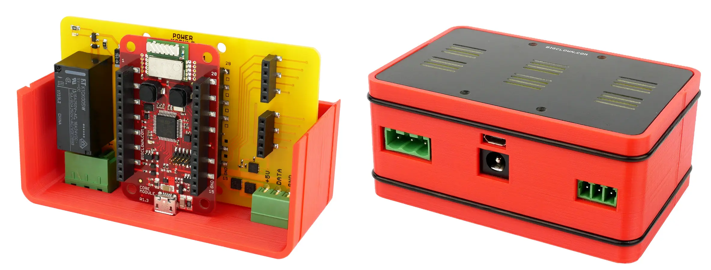
Step 5: Connect the LED strip to the pluggable socket on the right side
Step 6: Connect the 5V DC Power Jack
Playground Bootstrap
If you are using the new HARDWARIO Playground, then use the Functions tab instead of using http://localhost:1880/. Also the pairing process is now done in Devices tab. For communication test use the Messages tab.
Step 1: Open Node-RED in your web browser
Step 2: You should see the empty workspace with Flow 1
Step 3: Insert the following snippet in the flow (using Menu >> Import >> Clipboard) and click in Flow 1 tab, then deploy
[{"id":"2fc604fc.3b6abc","type":"inject","z":"dfc861b.b2a02a","name":"List all gateways","topic":"gateway/all/info/get","payload":"","payloadType":"str","repeat":"","crontab":"","once":false,"x":560,"y":460,"wires":[["a2c10833.24d5d8"]]},{"id":"1e4502b8.2f63fd","type":"inject","z":"dfc861b.b2a02a","name":"Start node pairing","topic":"gateway/usb-dongle/pairing-mode/start","payload":"","payloadType":"str","repeat":"","crontab":"","once":false,"x":570,"y":580,"wires":[["795ff5a7.8e266c"]]},{"id":"3d844ce2.932864","type":"inject","z":"dfc861b.b2a02a","name":"Stop node pairing","topic":"gateway/usb-dongle/pairing-mode/stop","payload":"","payloadType":"str","repeat":"","crontab":"","once":false,"x":560,"y":640,"wires":[["5967c452.c838bc"]]},{"id":"f202b253.2705b","type":"inject","z":"dfc861b.b2a02a","name":"List paired nodes","topic":"gateway/usb-dongle/nodes/get","payload":"","payloadType":"str","repeat":"","crontab":"","once":false,"x":560,"y":520,"wires":[["f0aca138.0b2c3"]]},{"id":"349f02fd.890f6e","type":"inject","z":"dfc861b.b2a02a","name":"Unpair all nodes","topic":"gateway/usb-dongle/nodes/purge","payload":"","payloadType":"str","repeat":"","crontab":"","once":false,"x":560,"y":700,"wires":[["2f1c5bb6.53d6f4"]]},{"id":"cf61d75d.4ad8f8","type":"mqtt in","z":"dfc861b.b2a02a","name":"","topic":"#","qos":"2","broker":"67b8de4a.029d3","x":530,"y":400,"wires":[["a5cb0658.f5d658"]]},{"id":"a5cb0658.f5d658","type":"debug","z":"dfc861b.b2a02a","name":"","active":true,"console":"false","complete":"false","x":790,"y":400,"wires":[]},{"id":"a2c10833.24d5d8","type":"mqtt out","z":"dfc861b.b2a02a","name":"","topic":"","qos":"","retain":"","broker":"717f7c18.ba0a24","x":770,"y":460,"wires":[]},{"id":"f0aca138.0b2c3","type":"mqtt out","z":"dfc861b.b2a02a","name":"","topic":"","qos":"","retain":"","broker":"717f7c18.ba0a24","x":770,"y":520,"wires":[]},{"id":"795ff5a7.8e266c","type":"mqtt out","z":"dfc861b.b2a02a","name":"","topic":"","qos":"","retain":"","broker":"717f7c18.ba0a24","x":770,"y":580,"wires":[]},{"id":"5967c452.c838bc","type":"mqtt out","z":"dfc861b.b2a02a","name":"","topic":"","qos":"","retain":"","broker":"717f7c18.ba0a24","x":770,"y":640,"wires":[]},{"id":"2f1c5bb6.53d6f4","type":"mqtt out","z":"dfc861b.b2a02a","name":"","topic":"","qos":"","retain":"","broker":"717f7c18.ba0a24","x":770,"y":700,"wires":[]},{"id":"67b8de4a.029d3","type":"mqtt-broker","z":"","broker":"127.0.0.1","port":"1883","clientid":"","usetls":false,"compatmode":true,"keepalive":"60","cleansession":true,"willTopic":"","willQos":"0","willPayload":"","birthTopic":"","birthQos":"0","birthPayload":""},{"id":"717f7c18.ba0a24","type":"mqtt-broker","z":"","broker":"127.0.0.1","port":"1883","clientid":"","usetls":false,"compatmode":true,"keepalive":"60","cleansession":true,"willTopic":"","willQos":"0","willPayload":"","birthTopic":"","birthQos":"0","birthPayload":""}]
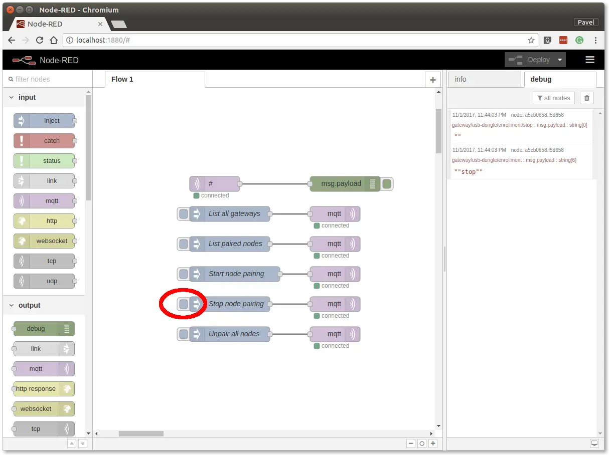
It will look like this:
This snippet provides control buttons for gateway/radio commands. These commands are sent over the MQTT protocol.
Step 4: Deploy the flow using the Deploy button in the top-right corner
Step 5: Open the debug tab
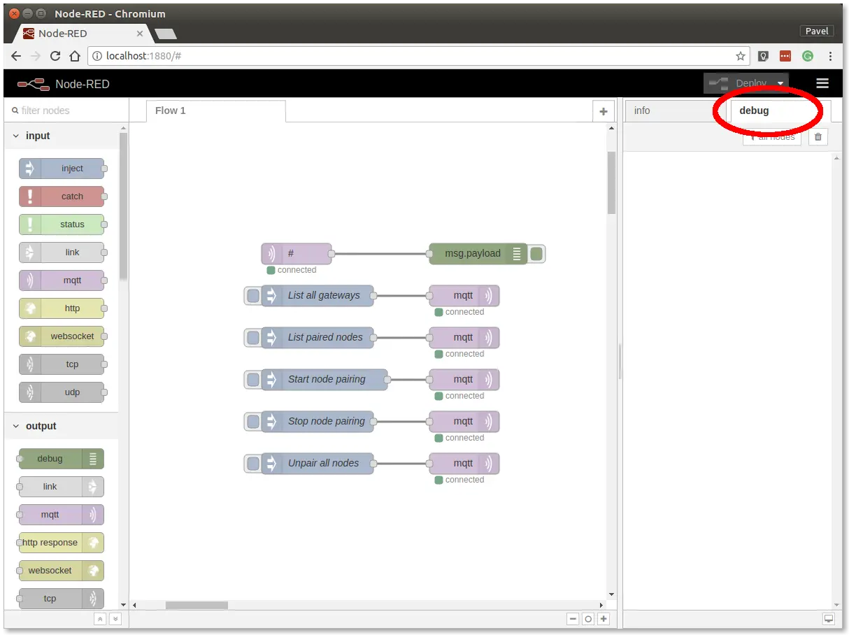
In the debug tab, you will be able to see all the MQTT messages.
Step 6: Click on the List all gateways button. You should see a response like this in the debug tab
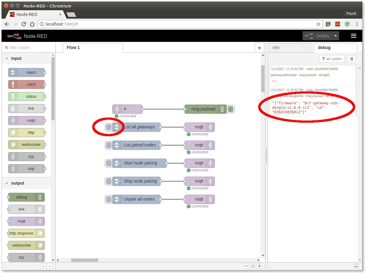
At this point, you've got working Node-RED, MQTT, HARDWARIO Radio Dongleand HARDWARIO Gateway.
Radio Pairing
In this section, we will create a radio link between the Radio Dongle and the Radio Smart LED strip.
Follow these steps in Node-RED:
Step 1: Click on the Start node pairing button
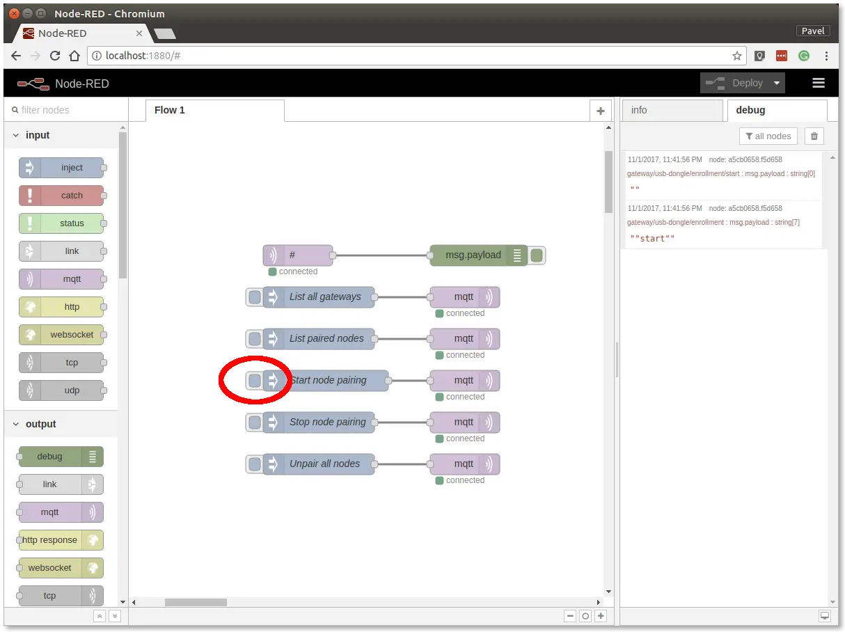
Step 2: Connect the power adapter into the Radio Power Controller to send the pairing request (you should also see the red LED on the Core Module to be on for about 2 seconds)
Step 3: Click on the Stop node pairing button
At this point, you've got established a radio link between the node (Radio Smart LED Strip) and the gateway (Radio Dongle).
Communication Test
Follow these steps in Node-RED:
Step 1: Switch to debug tab on the right
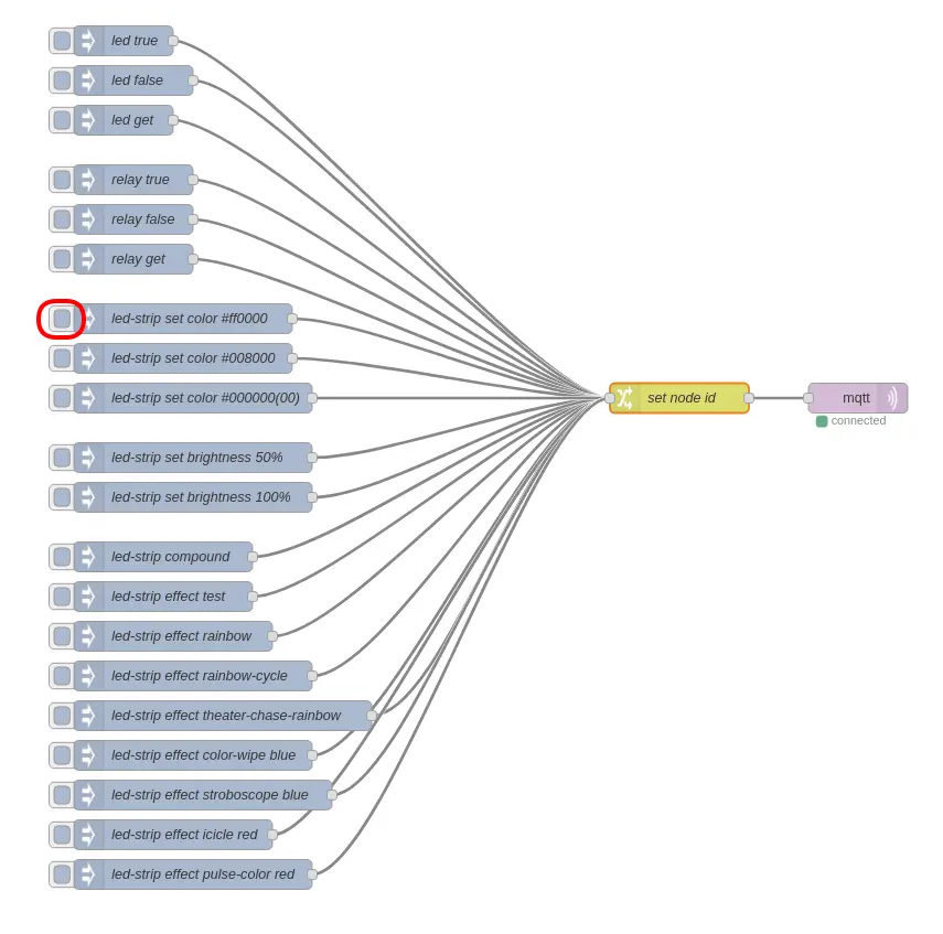
Step 2: Insert the following snippet in the flow (using Menu >> Import) and click in Flow 1 tab
[{"id":"c81deb91.e6df28","type":"inject","z":"6115d89b.b435c8","name":"led true","topic":"node/{id}/led/-/state/set","payload":"true","payloadType":"bool","repeat":"","crontab":"","once":false,"onceDelay":"","x":150,"y":40,"wires":[["fc940043.2c94c"]]},{"id":"e865057.ad650f8","type":"inject","z":"6115d89b.b435c8","name":"led false","topic":"node/{id}/led/-/state/set","payload":"false","payloadType":"bool","repeat":"","crontab":"","once":false,"onceDelay":"","x":160,"y":80,"wires":[["fc940043.2c94c"]]},{"id":"f4eda4ad.e61008","type":"inject","z":"6115d89b.b435c8","name":"relay true","topic":"node/{id}/relay/-/state/set","payload":"true","payloadType":"bool","repeat":"","crontab":"","once":false,"onceDelay":"","x":160,"y":180,"wires":[["fc940043.2c94c"]]},{"id":"d068e0ba.850d9","type":"inject","z":"6115d89b.b435c8","name":"relay false","topic":"node/{id}/relay/-/state/set","payload":"false","payloadType":"bool","repeat":"","crontab":"","once":false,"onceDelay":"","x":160,"y":220,"wires":[["fc940043.2c94c"]]},{"id":"4b02e13b.874a7","type":"inject","z":"6115d89b.b435c8","name":"led get","topic":"node/{id}/led/-/state/get","payload":"null","payloadType":"json","repeat":"","crontab":"","once":false,"onceDelay":"","x":150,"y":120,"wires":[["fc940043.2c94c"]]},{"id":"b8aadc82.6fb1a","type":"inject","z":"6115d89b.b435c8","name":"relay get","topic":"node/{id}/relay/-/state/get","payload":"null","payloadType":"json","repeat":"","crontab":"","once":false,"onceDelay":"","x":160,"y":260,"wires":[["fc940043.2c94c"]]},{"id":"39fb65a3.c426ea","type":"inject","z":"6115d89b.b435c8","name":"led-strip set color #ff0000","topic":"node/{id}/led-strip/-/color/set","payload":"\"#ff0000\"","payloadType":"str","repeat":"","crontab":"","once":false,"onceDelay":"","x":210,"y":320,"wires":[["fc940043.2c94c"]]},{"id":"c820ce88.576dd","type":"inject","z":"6115d89b.b435c8","name":"led-strip set color #008000","topic":"node/{id}/led-strip/-/color/set","payload":"\"#008000\"","payloadType":"str","repeat":"","crontab":"","once":false,"onceDelay":"","x":210,"y":360,"wires":[["fc940043.2c94c"]]},{"id":"edcffa41.db6bf8","type":"inject","z":"6115d89b.b435c8","name":"led-strip compound","topic":"node/{id}/led-strip/-/compound/set","payload":"[20, \"#ff0000\", 20, \"#ff7f00\", 20, \"#ffff00\", 20, \"#00ff00\", 20, \"#0000ff\", 20, \"#960082\", 24, \"#D500ff\"]","payloadType":"json","repeat":"","crontab":"","once":false,"onceDelay":"","x":190,"y":560,"wires":[["fc940043.2c94c"]]},{"id":"f145c1a6.00731","type":"inject","z":"6115d89b.b435c8","name":"led-strip effect test","topic":"node/{id}/led-strip/-/effect/set","payload":"{\"type\":\"test\"}","payloadType":"json","repeat":"","crontab":"","once":false,"onceDelay":"","x":190,"y":600,"wires":[["fc940043.2c94c"]]},{"id":"94faa725.2a6638","type":"inject","z":"6115d89b.b435c8","name":"led-strip effect rainbow","topic":"node/{id}/led-strip/-/effect/set","payload":"{\"type\":\"rainbow\", \"wait\":50}","payloadType":"json","repeat":"","crontab":"","once":false,"onceDelay":"","x":200,"y":640,"wires":[["fc940043.2c94c"]]},{"id":"50812ed8.45f09","type":"inject","z":"6115d89b.b435c8","name":"led-strip effect rainbow-cycle","topic":"node/{id}/led-strip/-/effect/set","payload":"{\"type\":\"rainbow-cycle\", \"wait\":50}","payloadType":"json","repeat":"","crontab":"","once":false,"onceDelay":"","x":220,"y":680,"wires":[["fc940043.2c94c"]]},{"id":"1c45c443.698d6c","type":"inject","z":"6115d89b.b435c8","name":"led-strip effect theater-chase-rainbow","topic":"node/{id}/led-strip/-/effect/set","payload":"{\"type\":\"theater-chase-rainbow\", \"wait\":50}","payloadType":"json","repeat":"","crontab":"","once":false,"onceDelay":"","x":250,"y":720,"wires":[["fc940043.2c94c"]]},{"id":"695dee35.ff264","type":"inject","z":"6115d89b.b435c8","name":"led-strip set brightness 50%","topic":"node/{id}/led-strip/-/brightness/set","payload":"50","payloadType":"str","repeat":"","crontab":"","once":false,"onceDelay":"","x":220,"y":460,"wires":[["fc940043.2c94c"]]},{"id":"f11b54bb.3fd3f8","type":"inject","z":"6115d89b.b435c8","name":"led-strip set brightness 100%","topic":"node/{id}/led-strip/-/brightness/set","payload":"100","payloadType":"str","repeat":"","crontab":"","once":false,"onceDelay":"","x":220,"y":500,"wires":[["fc940043.2c94c"]]},{"id":"efb0acf7.7808c","type":"inject","z":"6115d89b.b435c8","name":"led-strip effect color-wipe blue","topic":"node/{id}/led-strip/-/effect/set","payload":"{\"type\":\"color-wipe\", \"wait\":50, \"color\": \"#0000ff\"}","payloadType":"json","repeat":"","crontab":"","once":false,"onceDelay":"","x":220,"y":760,"wires":[["fc940043.2c94c"]]},{"id":"c2d7e432.c76cc8","type":"inject","z":"6115d89b.b435c8","name":"led-strip set color #000000(00)","topic":"node/{id}/led-strip/-/color/set","payload":"\"#000000(00)\"","payloadType":"str","repeat":"","crontab":"","once":false,"onceDelay":"","x":220,"y":400,"wires":[["fc940043.2c94c"]]},{"id":"e4691220.e3747","type":"mqtt out","z":"6115d89b.b435c8","name":"","topic":"","qos":"","retain":"","broker":"a6621c71.92f09","x":890,"y":400,"wires":[]},{"id":"fc940043.2c94c","type":"change","z":"6115d89b.b435c8","name":"set node id","rules":[{"t":"change","p":"topic","pt":"msg","from":"{id}","fromt":"str","to":"power-controller:0","tot":"str"}],"action":"","property":"","from":"","to":"","reg":false,"x":710,"y":400,"wires":[["e4691220.e3747"]]},{"id":"fcca537f.99cac","type":"inject","z":"6115d89b.b435c8","name":"led-strip effect stroboscope blue","topic":"node/{id}/led-strip/-/effect/set","payload":"{\"type\":\"stroboscope\", \"wait\":50, \"color\":\"#0000ff\"}","payloadType":"json","repeat":"","crontab":"","once":false,"onceDelay":"","x":230,"y":800,"wires":[["fc940043.2c94c"]]},{"id":"23fe88e4.4dc058","type":"inject","z":"6115d89b.b435c8","name":"led-strip effect icicle red","topic":"node/{id}/led-strip/-/effect/set","payload":"{\"type\":\"icicle\", \"wait\":50, \"color\":\"#ff0000\"}","payloadType":"json","repeat":"","crontab":"","once":false,"onceDelay":"","x":200,"y":840,"wires":[["fc940043.2c94c"]]},{"id":"811a0f5b.8f1ee","type":"inject","z":"6115d89b.b435c8","name":"led-strip effect pulse-color red","topic":"node/{id}/led-strip/-/effect/set","payload":"{\"type\":\"pulse-color\", \"wait\":200, \"color\":\"#ff0000\"}","payloadType":"json","repeat":"","crontab":"","once":false,"onceDelay":"","x":220,"y":880,"wires":[["fc940043.2c94c"]]},{"id":"a6621c71.92f09","type":"mqtt-broker","z":"","broker":"127.0.0.1","port":"1883","clientid":"","usetls":false,"compatmode":true,"keepalive":"60","cleansession":true,"birthTopic":"","birthQos":"0","birthPayload":"","willTopic":"","willQos":"0","willPayload":""}]
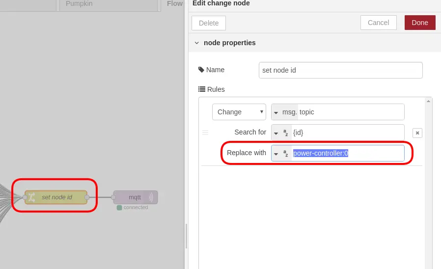
Step 3: Edit set node id node, and change "Replace with" to your node id, e.g. kit-power-controller:0 (you can find your node id by clicking on List paired nodes)
Step 4: Press led-strip set color #ff0000
Integration with Blynk IoT
Now that the Radio Power Controller is assembled and responding to the local colour test, let's control it from your phone with Blynk IoT (the current Blynk platform — the old Blynk Legacy cloud has been shut down). Everything here follows the canonical HARDWARIO Blynk IoT guide — open it alongside this page for the exact click paths and screenshots; below we only describe the mechanism.
In this project the data direction is app → device: each widget you tap in the Blynk IoT app writes a value to a Virtual Pin, Node-RED reads that pin, and forwards it to the LED strip / relay over the MQTT-out logic you already built.
Step 1: Create a Blynk IoT account, template and device
If you don't have one yet, create an account in the Blynk IoT app, then create a device template and a device from it. The guide walks through all of this; you can also reuse a template from a previous project. From the device detail, note its Auth Token and Template ID — you'll paste them into Node-RED in Step 4.
Step 2: Create a Datastream (Virtual Pin) for each control
On the template detail, open the Datastreams tab, click Edit, then + New Datastream and choose Virtual Pin. Create one Virtual Pin per control you want over the LED strip and the relay:
| Control | Virtual Pin | Datastream type | Sends to device |
|---|---|---|---|
| LED strip colour | V1 | String (colour) | led-strip/-/color/set |
| White level | V2 | Integer 0–255 | led-strip/-/color/set (white channel) |
| LED strip on/off | V3 | Integer 0/1 | led-strip/-/color/set (last colour / off) |
| Relay (power appliance) | V4 | Integer 0/1 | relay/-/state/set |
| Rainbow effect | V5 | Integer 0/1 | led-strip/-/effect/set (rainbow) |
| Theater-chase effect | V6 | Integer 0/1 | led-strip/-/effect/set (theater-chase-rainbow) |
| Brightness | V7 | Integer 0–100 | led-strip/-/brightness/set |
Save the template when you're done. (The Virtual Pin numbers above are just an example — use whatever free pins you like, but keep them consistent with the Node-RED nodes in Step 4.)
Step 3: Add the matching widgets in the Blynk IoT app
Download the Blynk IoT app from the App Store or Google Play, sign in, and open the device you created. On its dashboard add a widget for each Datastream and bind each widget to its Virtual Pin:
- Color widget → colour pin (V1)
- Slider widget → white level (V2) and another for brightness (V7)
- Button (switch mode) → on/off (V3) and the relay (V4)
- Button or Segmented Switch → rainbow effect (V5) and theater-chase effect (V6)
The guide shows exactly how to add and bind a widget.
Step 4: Read the Virtual Pins in Node-RED
Add a new flow in Node-RED. For each control, drop a Blynk IoT Read node (found under the Blynk IoT section in the left palette) and feed it into a small function node that maps the incoming value to the right MQTT topic, then into your existing MQTT out node. The mapping mirrors the local Communication Test topics — for example colour and white build a node/power-controller:0/led-strip/-/color/set payload, on/off restores the last colour or sends black, the relay sends node/power-controller:0/relay/-/state/set, the effects send node/power-controller:0/led-strip/-/effect/set, and brightness sends node/power-controller:0/led-strip/-/brightness/set.
Configure each Read node by clicking the pencil next to the connection and filling in:
- Url:
blynk.cloud - Auth Token and Template ID: the values from your device detail (Step 1)
Confirm with Add, then in the Virtual Pin field enter the pin number for that control (just the number, without the letter "V"). Confirm with Done.
Step 5: Deploy and try it
Click the red Deploy button in Node-RED, then open the device in the Blynk IoT app. Tap the widgets — the colour, white level, on/off, relay, effects and brightness should now drive the LED strip and the power appliance in real time. 🌈