Lesson 4 – Lights!
🧑💻 Duration: 40 minutes
🎯 Target audience: individuals and groups
1. Introduction
In HARDWARIO Playground, you can already find inputs, process them and write them to the Dashboard.
That gave you the basic skills for working with sensors and visualizing data.
In this lesson, you will play with an LED strip, which brings light into your work and opens up new creative possibilities.
2. What’s ready
✅ A prepared and paired Button Module or PIR Module
✅ Knowing how to work with messages in Playground (the Change and Switch nodes)
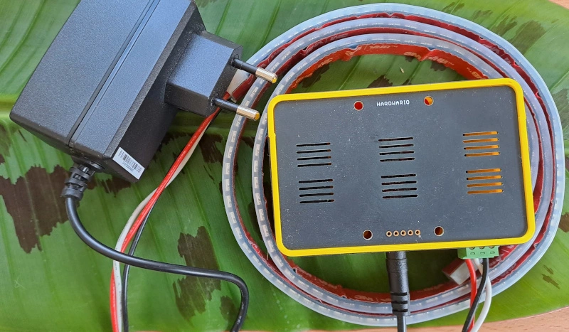
✅ A Power Module and an LED strip
3. Flash the Power Module firmware
- Connect the Power Module to your computer with a USB cable.
- On the Firmware tab, select the latest version.
- Mine had
twr-radio-power-controller-rgb150installed, but an update certainly won’t hurt.
- Mine had
- The LED strip does not need to be connected now, but it does no harm if it is.
4. Pair the Power Module
The Power Module differs from the other modules in that it has no batteries: it is powered directly from a power supply.
- On the Devices tab, click Start pairing.
- Connect the Power Module to the power supply. This switches it to pairing mode.
- After pairing, the Power Module reports as
power-controller:0.
5. Start it up!
Once again, start the flow with an input that sends messages. There are several options:
✅ Button Module: watching for a button press
✅ PIR Module: watching the orientation
✅ Any module: they all measure temperature (the option for the patient 😊)
6. What to send to the Power Module
So far, you have used the mqtt in node to read from sensors.
Now we need to write to the device → we use mqtt out.
A topic that lights up the strip is, for example: node/power-controller:0/led-strip/-/color/set
7. What message to send
If you connect an input (for example Button with the message 1) directly to an output (the strip setting), it will not work correctly.
That is why you use a Change node and set msg.payload in it to a color in hexadecimal RGB code (for example red: "#FF0000").
👉 If you don’t know RGB color codes, look them up in a color table.

8. Playing with code
This is how you build code that changes the LED strip color according to the PIR sensor orientation:
- Add a Switch node.
- Set a different color (
msg.payload) for each orientation (1–6). - Send it to the Power Module through mqtt out.

9. Colors and effects
It would be a shame not to use the strip to the full. Try, for example, the command node/power-controller:0/led-strip/-/effect/set with this message:
{"type":"rainbow", "wait":10}
Are your eyes hurting from too much brightness? node/power-controller:0/led-strip/-/brightness/set takes a value from 0–100 as the message and sets the brightness accordingly.
10. Addressing
You can also address the strip in sections, down to single LEDs. The topic for this is node/power-controller:0/led-strip/-/compound/set. The message holds a list of pairs: the number of LEDs and their color. For example, this message lights the first 20 LEDs red and the next 20 green:
[20, "#ff0000", 20, "#00ff00"]
11. Summary
You have paired the Power Module with the LED strip firmware.
You can light up the LED strip in different colors and even add effects.