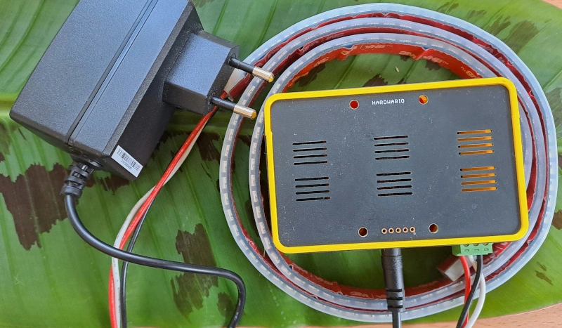
Turn on the LED strip
3. Flash Firmware for the Power Module
- Connect the Power Module using a USB cable.
- In the Firmware tab, select the latest version.
- Mine had
twr-radio-power-controller-rgb150installed, but it’s definitely good to update it.
- Mine had
- The LED strip does not need to be connected at this moment, but it won’t cause any issues if it is.
4. Pair the Power Module
The Power Module is unique in that it does not have batteries – it is powered directly from a power source.
- In the Devices tab, click Start pairing.
- Plug the Power Module into the power source – this puts it into pairing mode.
- After pairing, the Power Module appears as
power-controller:0.
5. Start It Up!
Programming in the flow again begins with a message that triggers something. There are several options:
✅ Button module – monitoring a button press
✅ PIR module – monitoring orientation
✅ Any module – all of them have temperature, which you can change (a more patient option 😊)
6. What to Send to the Power Module
So far, you have used the mqtt in node to read from sensors.
Now we need to write to the device → we use mqtt out.
The topic that lights up the strip, for example, is: node/power-controller:0/led-strip/-/color/set
7. What Message to Send
Directly connecting an input (e.g., Button with message 1) to an output (LED strip setting) won’t lead to the desired result.
Therefore, use a Change node, where you reassign msg.payload to a color value in RGB hex code (for example, red: "#FF0000").
👉 If you’re not familiar with RGB color coding, we recommend checking available color tables.

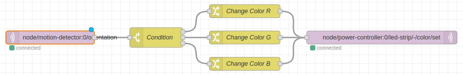
8. Playing with Code
For code that can change the LED strip color based on PIR sensor orientation:
- Add a Switch node.
- According to orientation (1–6), set a different color (
msg.payload). - Send it via mqtt out to the Power Module.