Radio Flood Detector
This guide walks you through the Radio Flood Detector project. You'll work with the detector in Node-RED, and when it detects a water leak, the IFTTT service sends a push notification to your smartphone.
Block Diagram
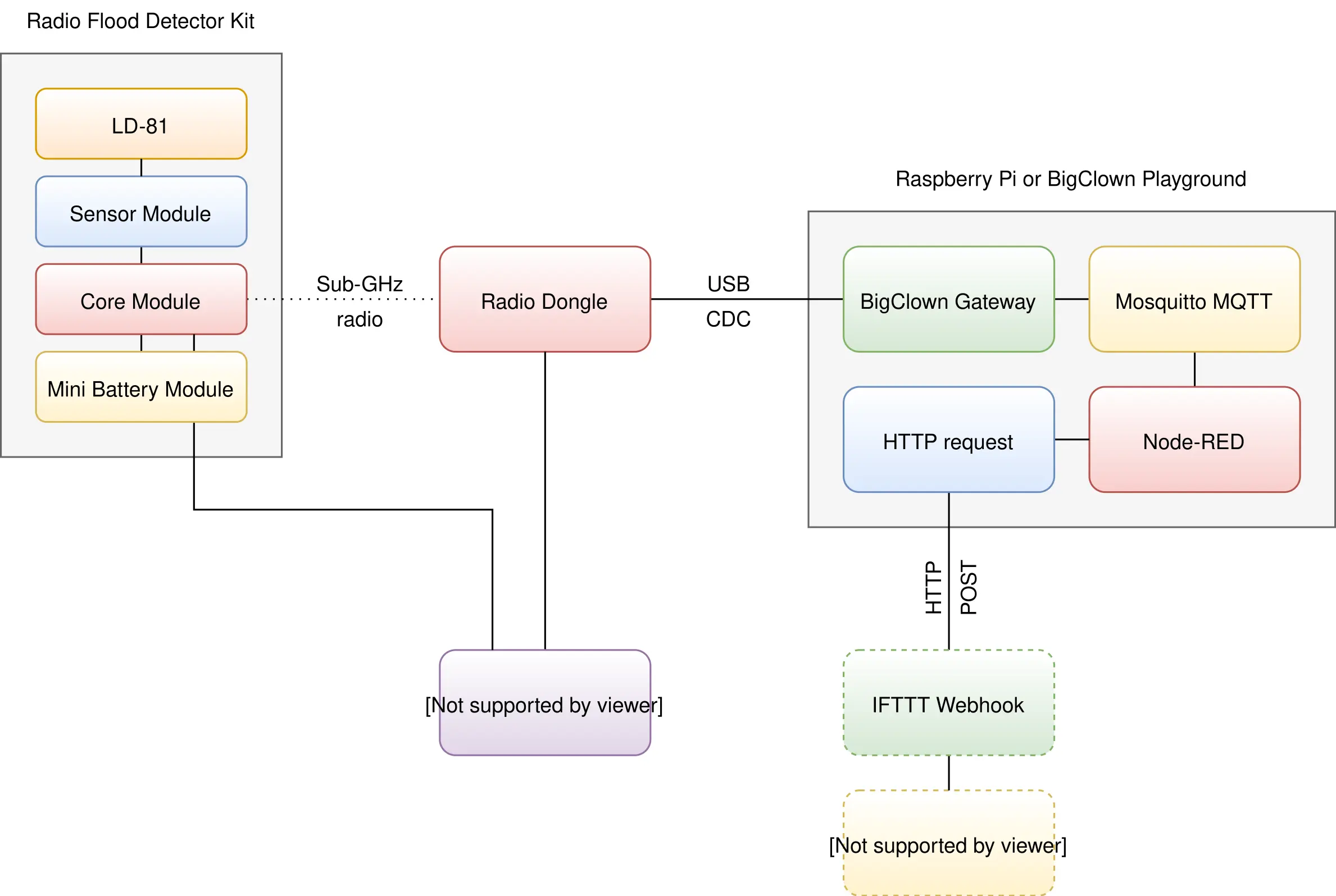
Requirements
- Either the HARDWARIO Radio Flood Detector Kit or these individual components:
- 1x HARDWARIO LD-81
- 1x HARDWARIO Sensor Module
- 1x HARDWARIO Core Module
- 1x HARDWARIO Mini Battery Module
- 1x HARDWARIO Radio Dongle
- One of the following:
-
HARDWARIO Playground installed (recommended)
See Playground Installation for details.
-
Raspberry Pi with the HARDWARIO Raspbian distribution
See Raspberry Pi Installation for details.
-
HARDWARIO Firmware Tool installed
See Firmware Flashing Tool for details.
-
Firmware Upload
You'll upload the firmware to the Core Module with HARDWARIO Playground.
Step 1: Connect the Core Module to your computer with a Micro USB cable
Step 2: Flash the firmware
Start HARDWARIO Playground, select the hardwario/twr-radio-flood-detector firmware on the Firmware tab and upload it to the Core Module. The firmware appears in the list only after you tick Show all.
Flashing Core Module R1 and R2 The older Core Module 1 and the newer Core Module 2 are flashed differently; see Core Module R1 and R2 comparison in the Hardware section.
Step 3: Disconnect the Micro USB cable from the Core Module and the computer
Your firmware is now uploaded.
Hardware Assembly
Watch this short video for a simple step-by-step demonstration:
Step 1: Start with the Mini Battery Module
Step 2: Plug the Core Module onto the Mini Battery Module
Playground Setup
If you use the new HARDWARIO Playground, open the Functions tab instead of http://localhost:1880/. Pairing now happens on the Devices tab, and you test communication on the Messages tab.
Step 1: Open Node-RED in your web browser
Step 2: You should see an empty workspace with Flow 1
Step 3: Import the following snippet into the flow (Menu >> Import) and click the Flow 1 tab
[{"id":"2fc604fc.3b6abc","type":"inject","z":"dfc861b.b2a02a","name":"List all gateways","topic":"gateway/all/info/get","payload":"","payloadType":"str","repeat":"","crontab":"","once":false,"x":560,"y":460,"wires":[["a2c10833.24d5d8"]]},{"id":"1e4502b8.2f63fd","type":"inject","z":"dfc861b.b2a02a","name":"Start node pairing","topic":"gateway/usb-dongle/pairing-mode/start","payload":"","payloadType":"str","repeat":"","crontab":"","once":false,"x":570,"y":580,"wires":[["795ff5a7.8e266c"]]},{"id":"3d844ce2.932864","type":"inject","z":"dfc861b.b2a02a","name":"Stop node pairing","topic":"gateway/usb-dongle/pairing-mode/stop","payload":"","payloadType":"str","repeat":"","crontab":"","once":false,"x":560,"y":640,"wires":[["5967c452.c838bc"]]},{"id":"f202b253.2705b","type":"inject","z":"dfc861b.b2a02a","name":"List paired nodes","topic":"gateway/usb-dongle/nodes/get","payload":"","payloadType":"str","repeat":"","crontab":"","once":false,"x":560,"y":520,"wires":[["f0aca138.0b2c3"]]},{"id":"349f02fd.890f6e","type":"inject","z":"dfc861b.b2a02a","name":"Unpair all nodes","topic":"gateway/usb-dongle/nodes/purge","payload":"","payloadType":"str","repeat":"","crontab":"","once":false,"x":560,"y":700,"wires":[["2f1c5bb6.53d6f4"]]},{"id":"cf61d75d.4ad8f8","type":"mqtt in","z":"dfc861b.b2a02a","name":"","topic":"#","qos":"2","broker":"67b8de4a.029d3","x":530,"y":400,"wires":[["a5cb0658.f5d658"]]},{"id":"a5cb0658.f5d658","type":"debug","z":"dfc861b.b2a02a","name":"","active":true,"console":"false","complete":"false","x":790,"y":400,"wires":[]},{"id":"a2c10833.24d5d8","type":"mqtt out","z":"dfc861b.b2a02a","name":"","topic":"","qos":"","retain":"","broker":"717f7c18.ba0a24","x":770,"y":460,"wires":[]},{"id":"f0aca138.0b2c3","type":"mqtt out","z":"dfc861b.b2a02a","name":"","topic":"","qos":"","retain":"","broker":"717f7c18.ba0a24","x":770,"y":520,"wires":[]},{"id":"795ff5a7.8e266c","type":"mqtt out","z":"dfc861b.b2a02a","name":"","topic":"","qos":"","retain":"","broker":"717f7c18.ba0a24","x":770,"y":580,"wires":[]},{"id":"5967c452.c838bc","type":"mqtt out","z":"dfc861b.b2a02a","name":"","topic":"","qos":"","retain":"","broker":"717f7c18.ba0a24","x":770,"y":640,"wires":[]},{"id":"2f1c5bb6.53d6f4","type":"mqtt out","z":"dfc861b.b2a02a","name":"","topic":"","qos":"","retain":"","broker":"717f7c18.ba0a24","x":770,"y":700,"wires":[]},{"id":"67b8de4a.029d3","type":"mqtt-broker","z":"","broker":"127.0.0.1","port":"1883","clientid":"","usetls":false,"compatmode":true,"keepalive":"60","cleansession":true,"willTopic":"","willQos":"0","willPayload":"","birthTopic":"","birthQos":"0","birthPayload":""},{"id":"717f7c18.ba0a24","type":"mqtt-broker","z":"","broker":"127.0.0.1","port":"1883","clientid":"","usetls":false,"compatmode":true,"keepalive":"60","cleansession":true,"willTopic":"","willQos":"0","willPayload":"","birthTopic":"","birthQos":"0","birthPayload":""}]
It looks like this:
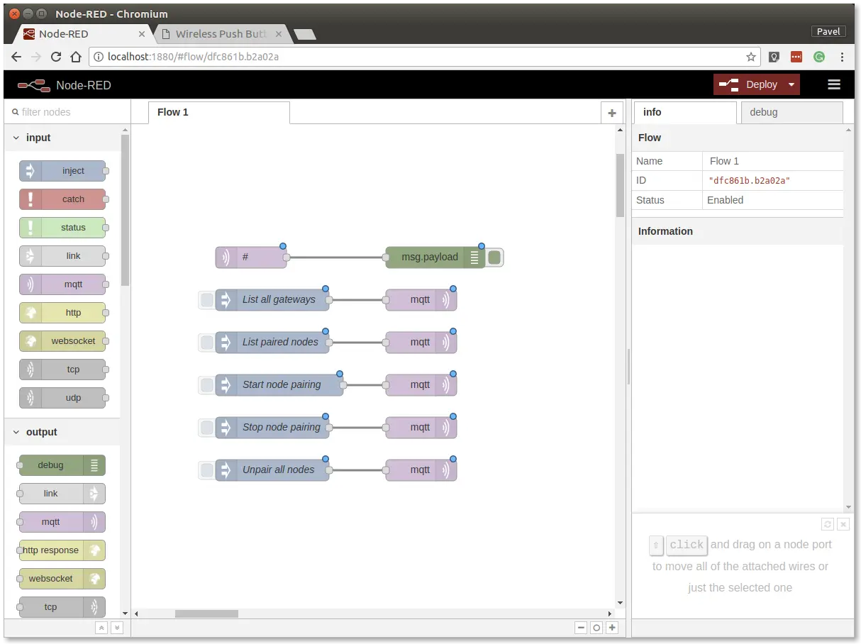
The snippet adds buttons for the gateway and radio commands, which are sent over MQTT.
Step 4: Deploy the flow with the Deploy button in the top-right corner
Step 5: Open the debug tab
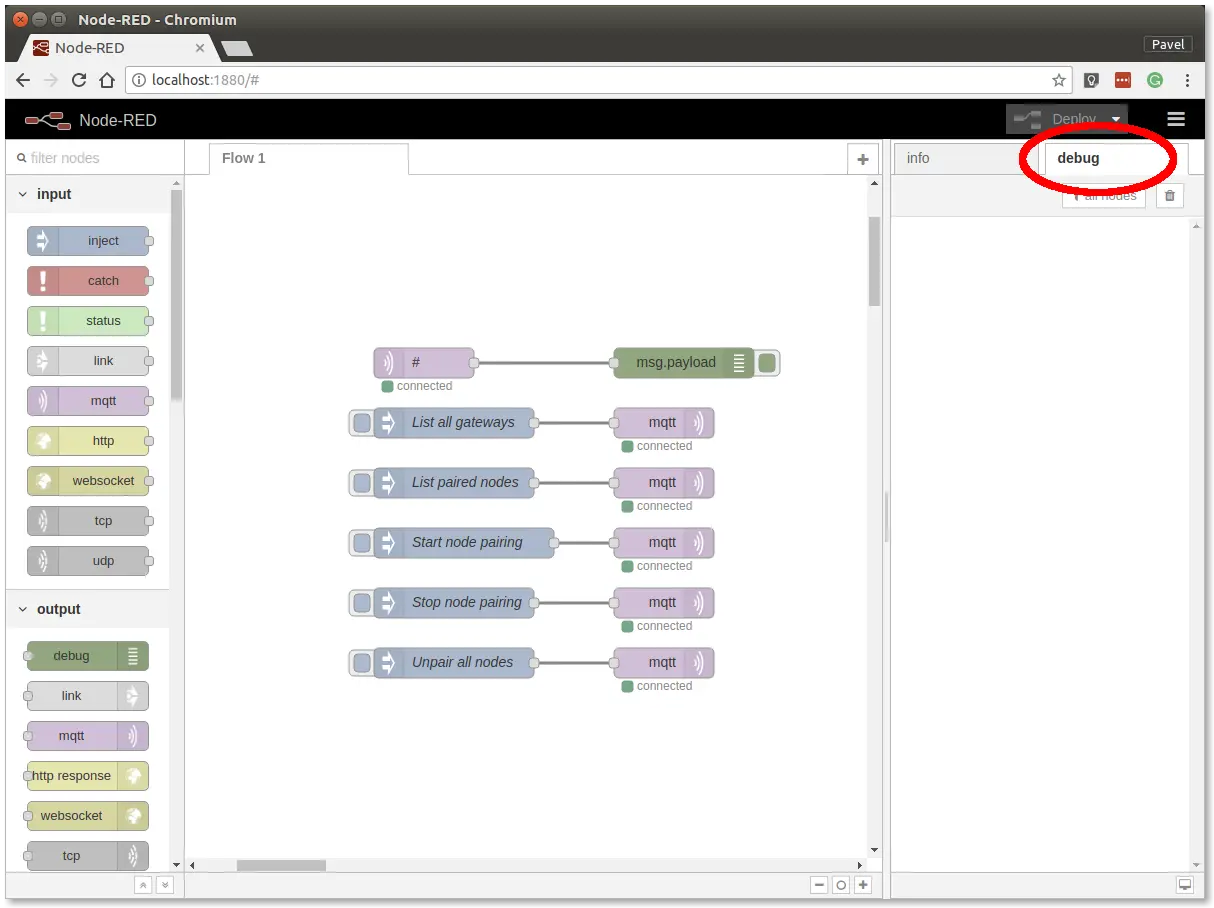
The debug tab shows all MQTT messages.
Step 6: Click the List all gateways button. The debug tab should show a response like this
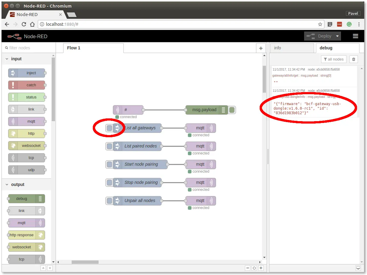
You now have working Node-RED, MQTT, HARDWARIO Radio Dongle and HARDWARIO Gateway.
Radio Pairing
In this section, we'll establish a radio link between the Radio Dongle and the Radio Flood Detector.
In Node-RED, follow these steps:
Step 1: Click the Start node pairing button
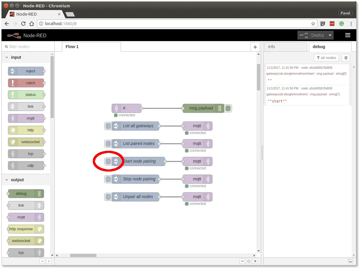
Step 2: Insert the batteries into the Radio Flood Detector to send the pairing request (the red LED on the Core Module should also light up for about 2 seconds)
Step 3: Click the Stop node pairing button
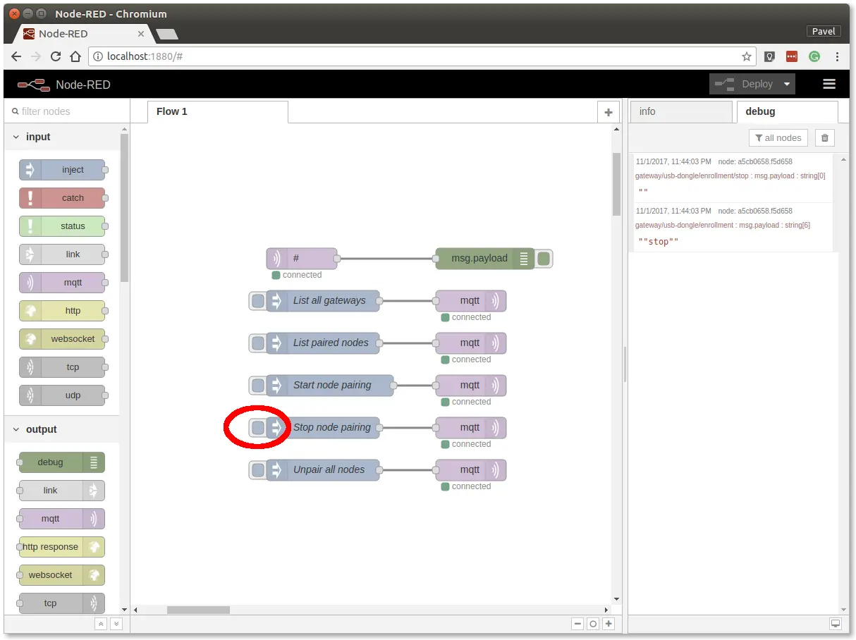
You now have a radio link between the node (Radio Flood Detector) and the gateway (Radio Dongle).
Communication Test
In Node-RED, follow these steps:
Step 1: Switch to the debug tab on the right
Step 2: Dip the LD-81 flood sensor into a glass of water to trigger a radio transmission
You should then see messages like these:
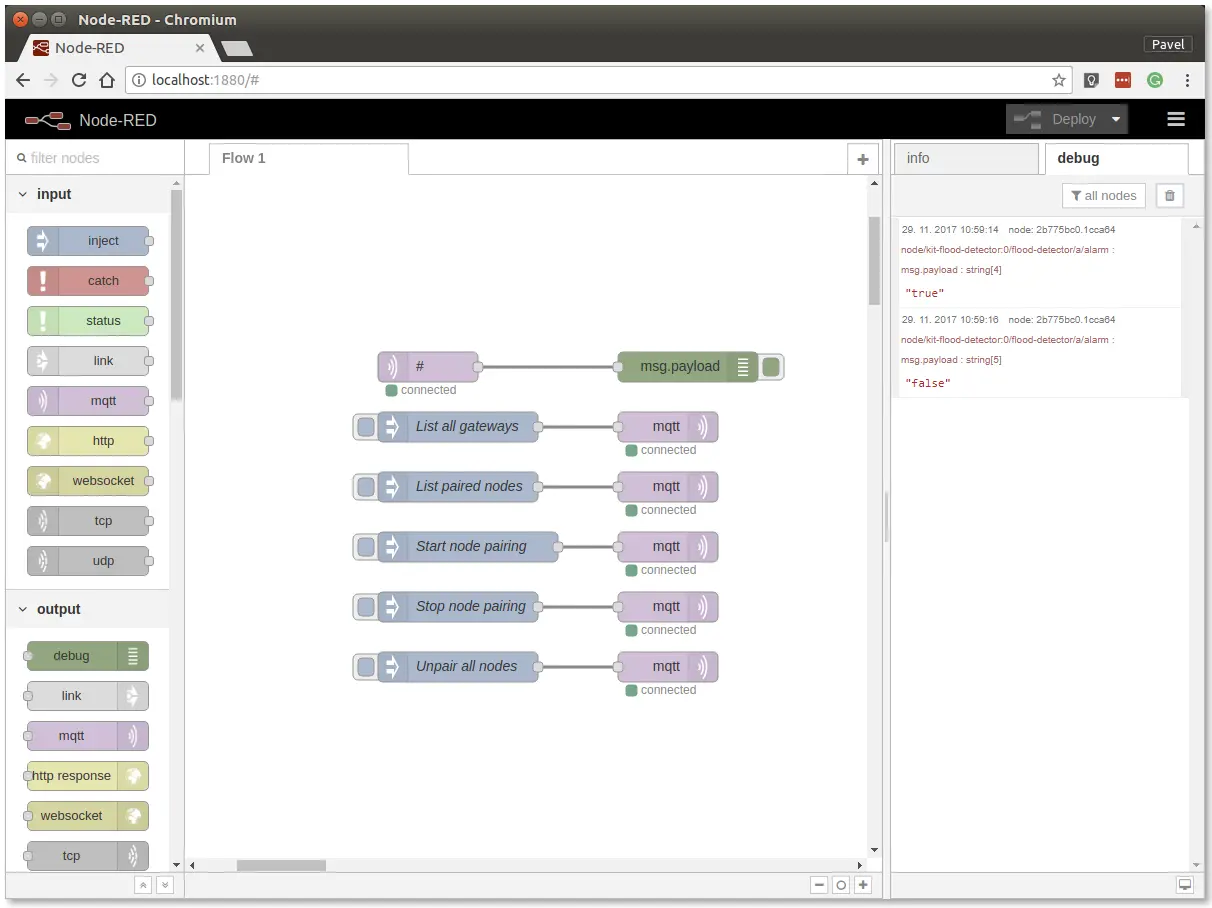
Radio communication is now verified.
Enclosure
If you have a suitable enclosure, you can put the assembly into it.
You'll find enclosures for TOWER kits in the Enclosures category of the HARDWARIO Store.
Integration with IFTTT
In this section, we'll create an Applet in the IFTTT service. An Applet is a rule that responds to an event with an action.
Step 1: Open a web browser and go to IFTTT

Step 2: Sign in to IFTTT. You can also sign up with your Google or Facebook account
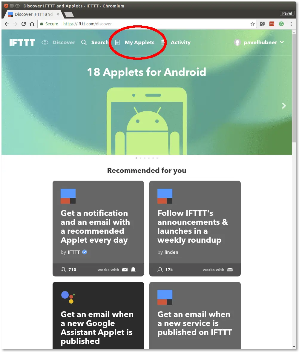
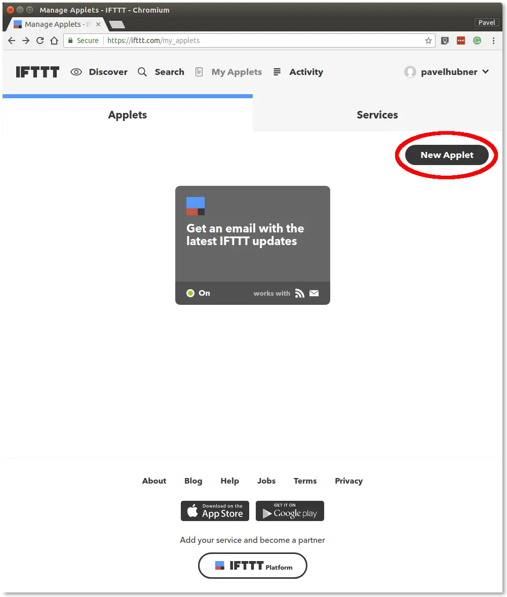
Step 3: Go to My Applets in the menu and click the New Applet button
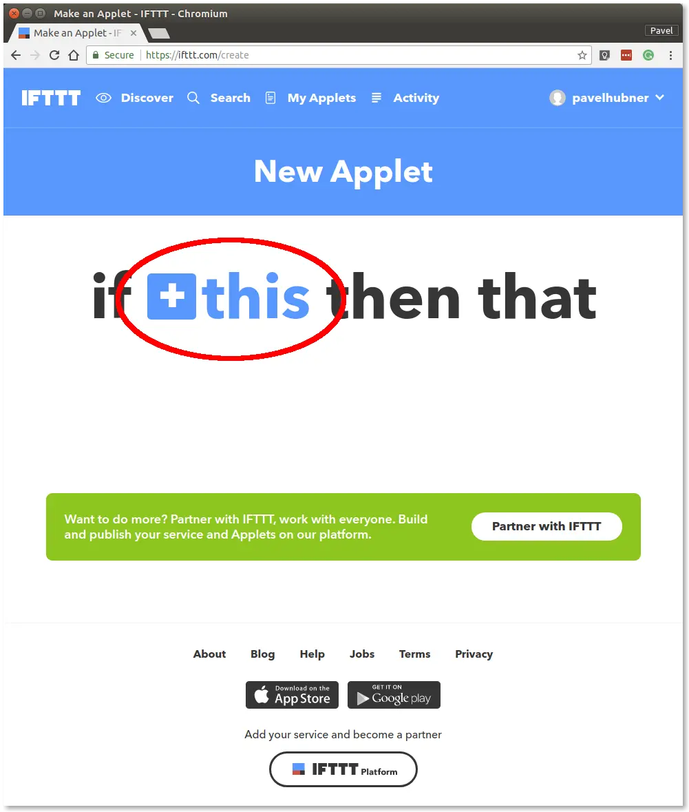
Step 4: Click +this in the if this then that sentence
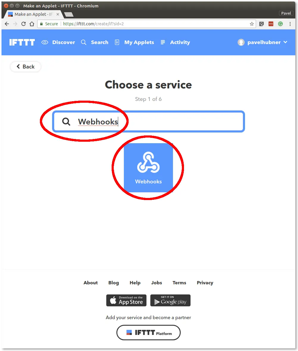
Step 5: Search for the Webhooks service and select it
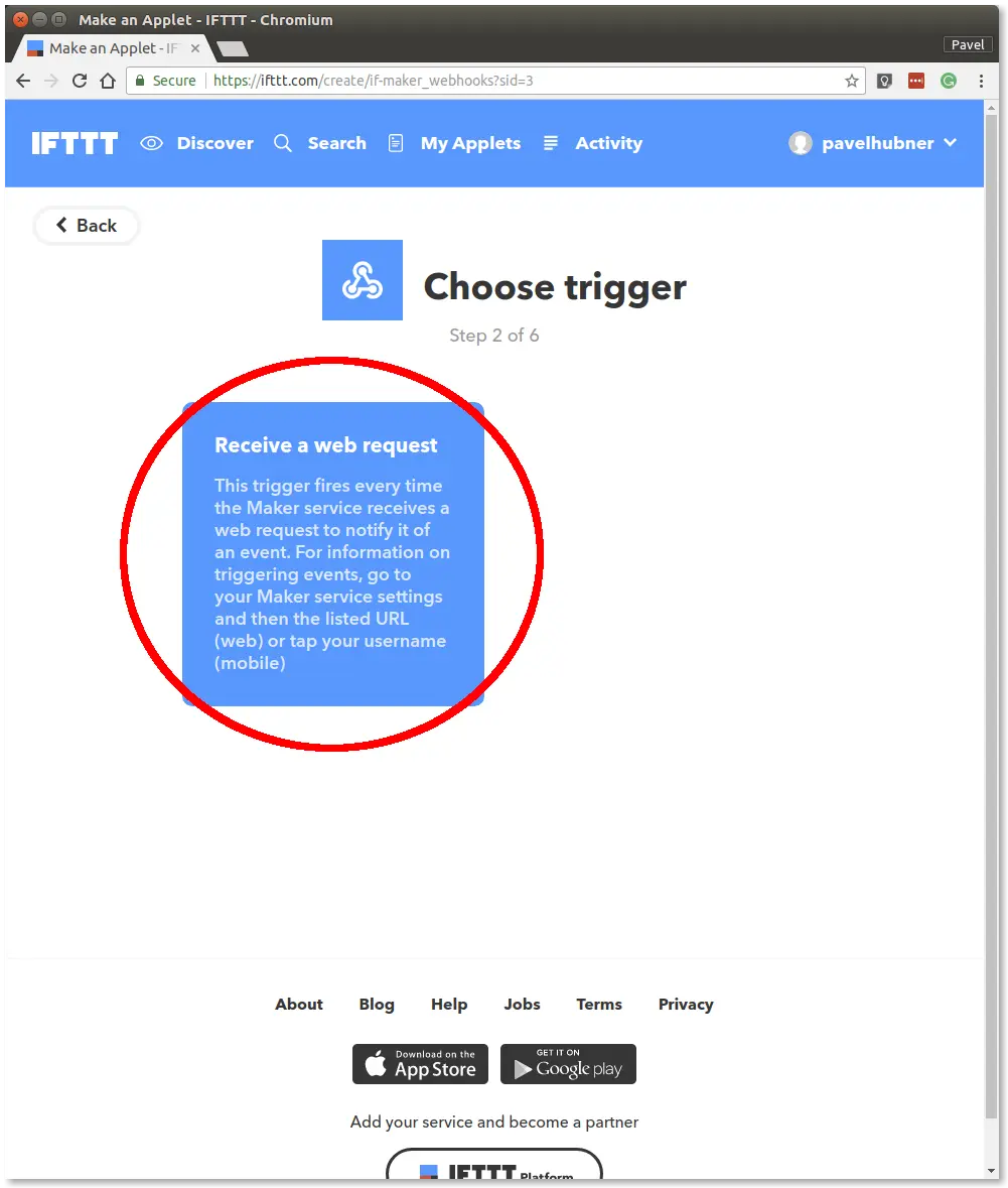
Step 6: Click Receive a web request
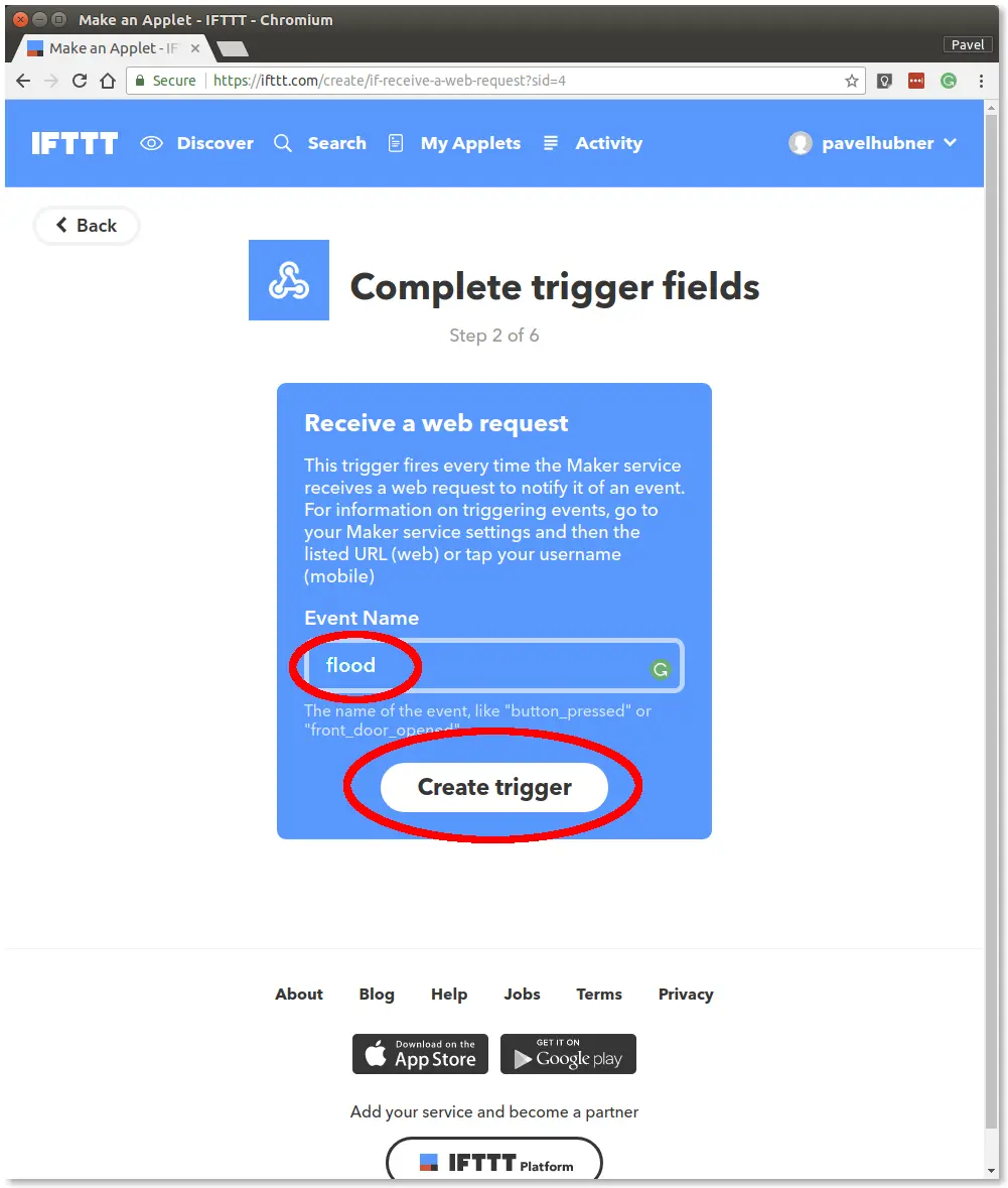
Step 7: Type flood in the Event Name field and click Create Trigger
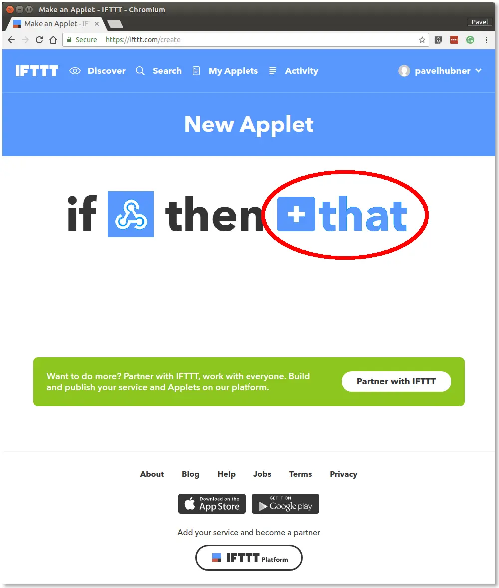
Step 8: Click +that in the if this then that sentence
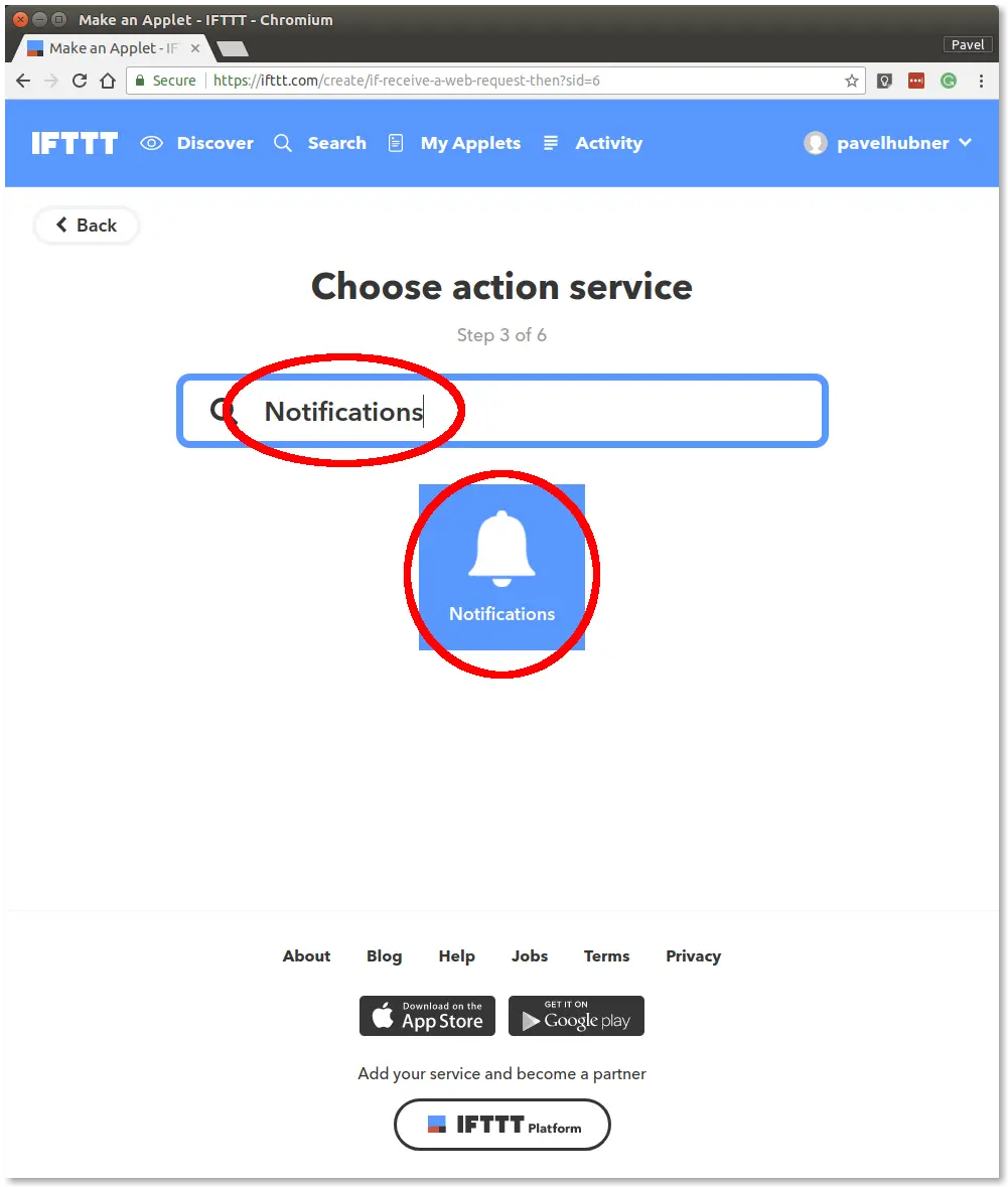
Step 9: Search for the Notifications action service and select it
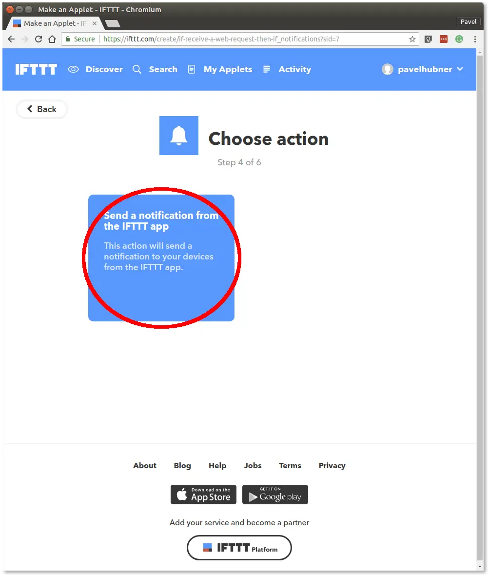
Step 10: Click Send a notification from the IFTTT app
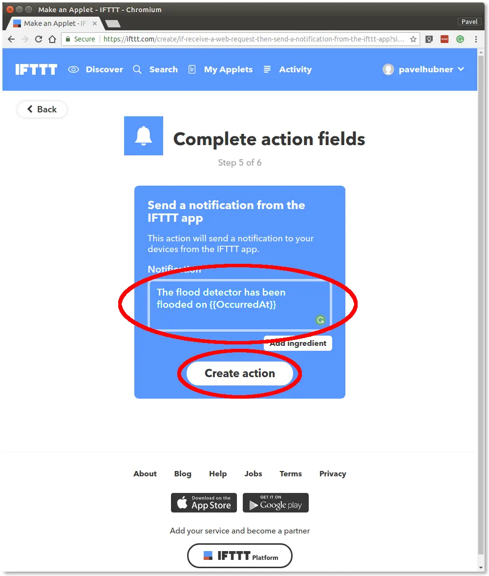
Step 11: Enter the text The flood detector has been flooded on {{OccurredAt}} in the Notification field and click the Create action button
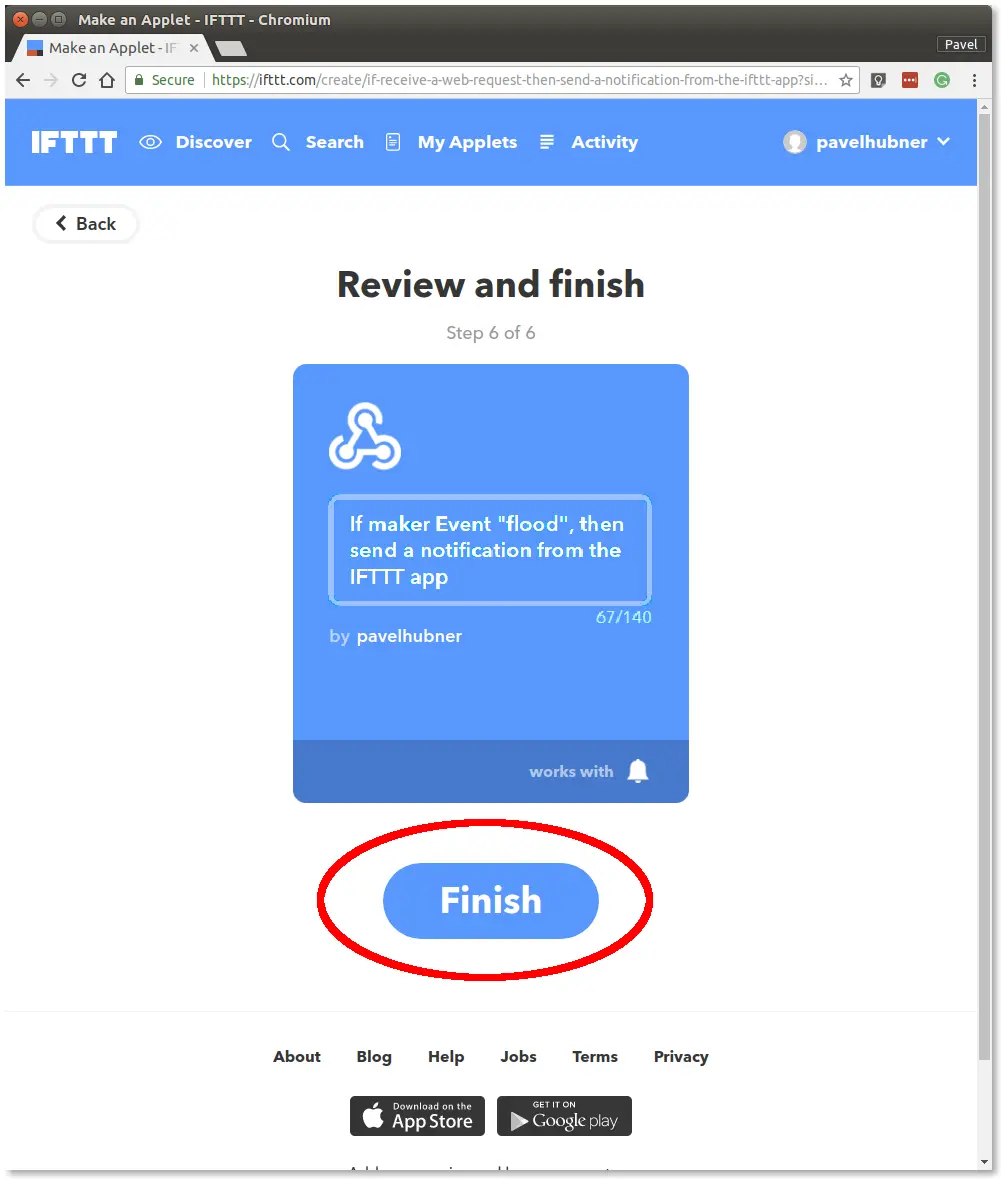
Step 12: Click the Finish button
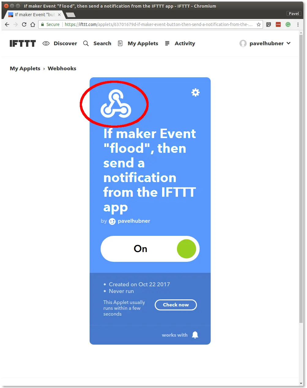
Step 13: Click the Webhooks button
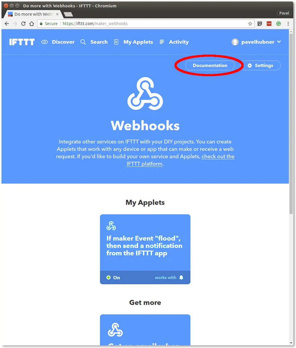
Step 14: Click the Documentation button
Step 15: Click the event field
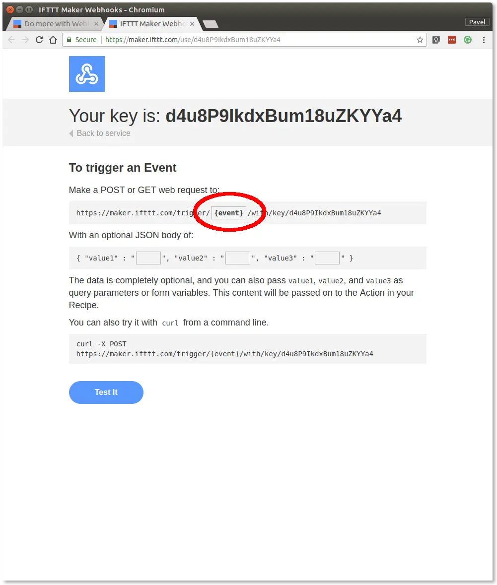
Step 16: Enter flood in the event field and keep the window open
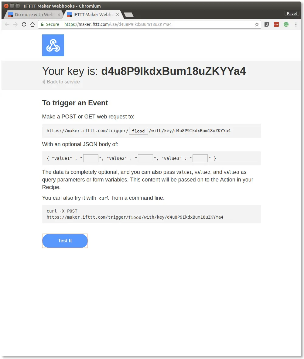
Step 17: Install the IFTTT app on your smartphone and sign in with the account you used to create the applet. When the app asks, allow push notifications
Step 18: Click the Test It button in the browser window
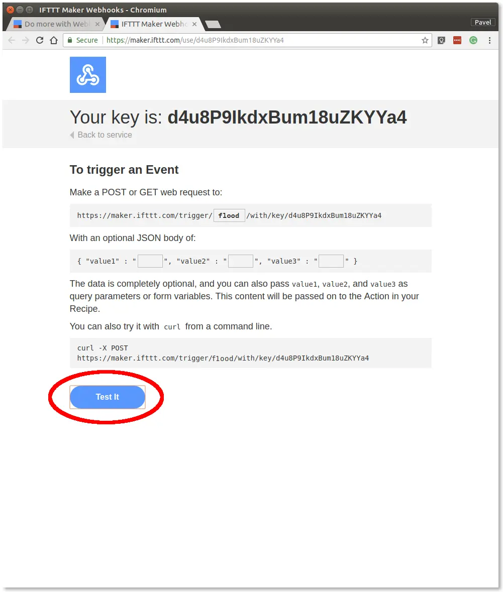
Step 19: A push notification should arrive on your smartphone within a few seconds
Step 20: Copy the key to the clipboard; you'll need it later
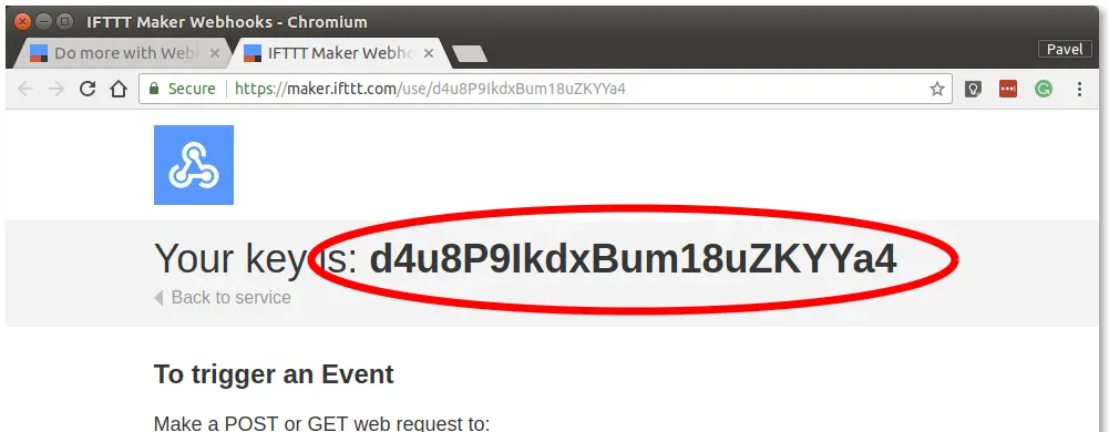
You now have a working notification Applet in the IFTTT service.
Connect Node-RED to IFTTT
In this section, we'll link the flood event on MQTT to an HTTP request to IFTTT, which triggers the push notification.
Step 1: Switch to your Node-RED flow
Step 2: Import the following snippet into the flow (Menu >> Import)
[{"id":"c6ce743.f65db88","type":"mqtt in","z":"d5a82106.8d3fa","name":"","topic":"node/flood-detector:0/flood-detector/a/alarm","qos":"2","broker":"29fba84a.b2af58","x":240,"y":140,"wires":[["7d9c308c.edf04"]]},{"id":"7d9c308c.edf04","type":"switch","z":"d5a82106.8d3fa","name":"","property":"payload","propertyType":"msg","rules":[{"t":"eq","v":"true","vt":"str"}],"checkall":"true","repair":false,"outputs":1,"x":510,"y":140,"wires":[["e2287fd0.90124"]]},{"id":"e2287fd0.90124","type":"ifttt out","z":"d5a82106.8d3fa","eventName":"flood","key":"40c1e6be.8cb228","x":670,"y":140,"wires":[]},{"id":"29fba84a.b2af58","type":"mqtt-broker","z":"","broker":"127.0.0.1","port":"1883","clientid":"","usetls":false,"compatmode":true,"keepalive":"60","cleansession":true,"birthTopic":"","birthQos":"0","birthPayload":"","willTopic":"","willQos":"0","willPayload":""},{"id":"40c1e6be.8cb228","type":"ifttt-key","z":""}]
It looks like this:

The snippet connects the MQTT topic node/flood-detector:0/flood-detector/a/alarm to the IFTTT service. Before the message goes to IFTTT, we have to let only true events through.
Step 3: Double-click the IFTTT node and enter the IFTTT key you got in the previous section

Step 4: Save the settings with the Done button
Step 5: Deploy the flow with the Deploy button in the top-right corner
You should now get a push notification whenever you bridge the flood sensor contacts with damp fingers or dip them in water.